13
General Monitors recommends the use of shielded cable generally, though in some
cases it is not an absolute necessity. Due to the low levels of sensor signal voltages,
shielded cable is required in some installations to guard against extraneous electrical
noise. The shield must be enclosed in a suitable insulat ing o uter j ac ket and must b e
grounded only at the rear-panel sensor-shield ground terminal. Care must be taken to
assure that the shield does not contact the sensor housing or metal conduit.
CAUTION: Avoid running sensor cables close to high power cables, radio transmission
lines, or cables subject to pulses of high current.
Sensor cable connections must be crimped and SOLDERED for stable operation. Use
only continuous, un-spliced cable runs if possible. Improperly spliced cable can res ult in
corrosion, resistance changes, and drift.
To Connect the Cable at the Sensor:
1. Remove the P/N 10252-1 housing lid to reveal the terminal strip. The sensor is
connected in the housing according to the color designations. (The green
position is not used).
2. Sensor cables are connected at the controller to the terminal blocks located
along the top of the rear of the controller. The channel numbers (1,2,3 & 4) read
f rom right to left on these sets of terminals.
3. Connect the cable so that the terminal color at the sensor housing matches the
terminal color at the controller as follows:
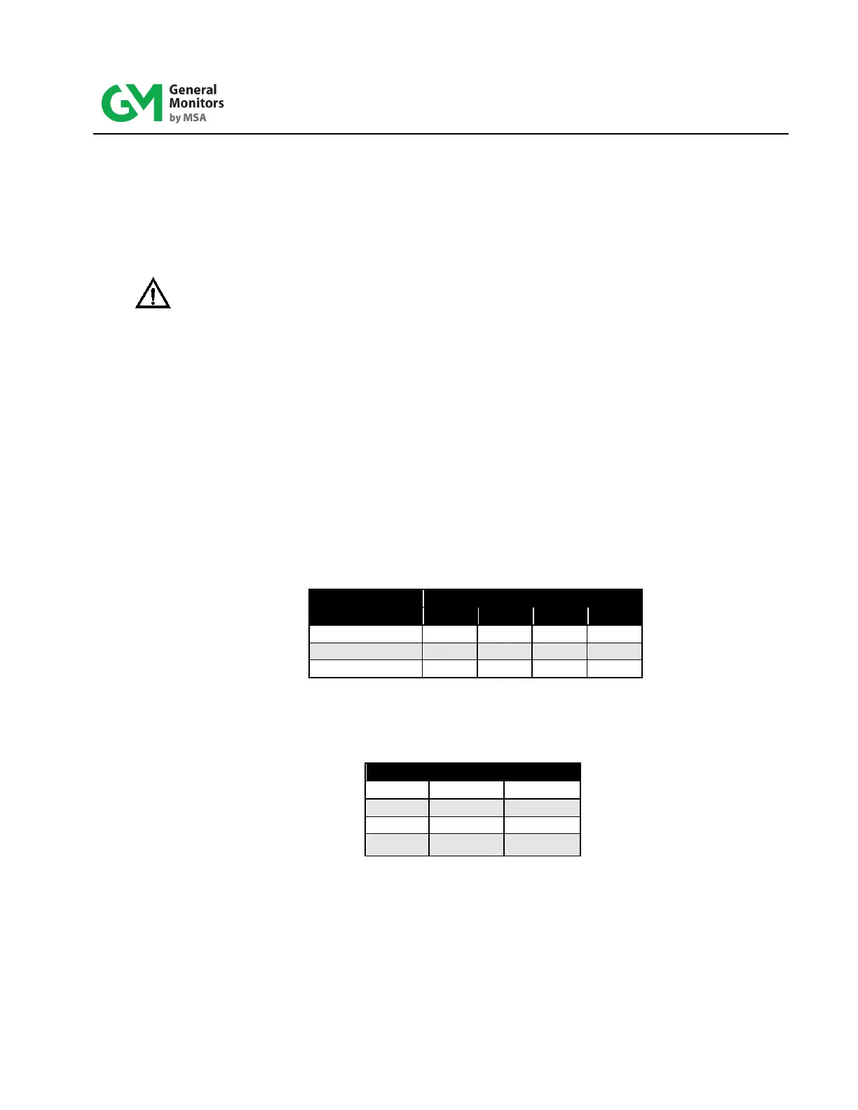
WIRE COLOR
Table 2: Terminal Colors
4. Cable runs should not exceed the following distances (maximum loop resistance
of 40-Ohms):
Table 3: Maximum Cable Run Distance