20
When a channel is in the Calibration, Calibration Check, Setup or Setup Check modes, a
1.5mA signal is generated by this output. During Calibration mode, the digital display
shows prompts associated with the calibration procedure. During Calibration Check
mode, the digital display shows the gas concentration as a flashing digit, or pair of digits.
When a channel enters into a f ault condition a 0mA signal is generated by this output.
During a f ault, the display shows a fault code.
If the sensor attached to the channel is seeing gas in excess of 100% of f ull s cale, t he
output generates a signal between 20 and 21.7mA (not proportional).
3.5 Calibration Check Mode
To perform a calibration check, use the following procedure:
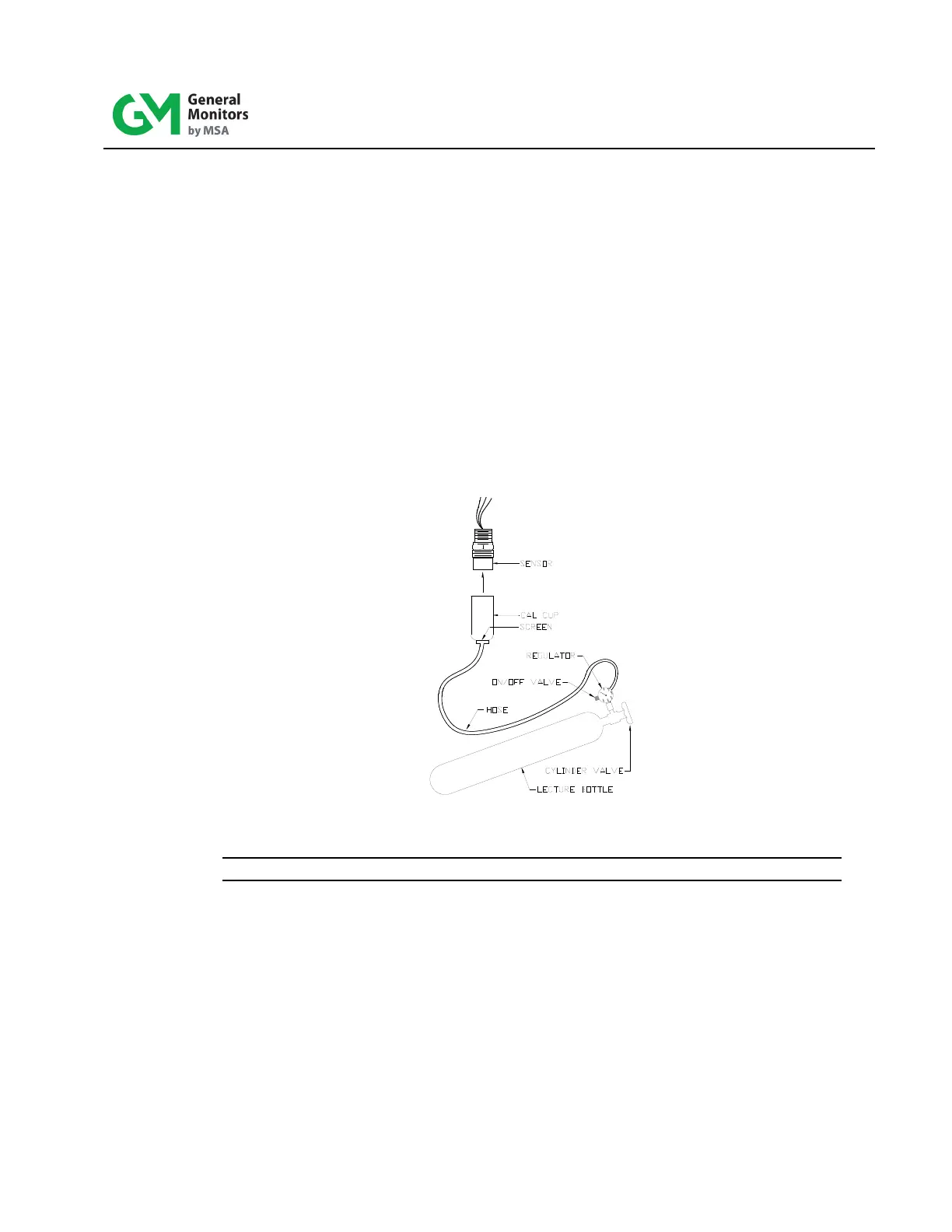
1. Place the cup from the portable purge calibrator over the sensor.
Figure 9: Portable Purge Calibrator
NOTE: The Calibration Check mode cannot be entered if the channel is in alarm.
2. Enter the Calibration Check mode by pressing and holding the Mode button until t he
CAL LED begins to flash (about ten seconds). The channel displays the calibrat ion
level. When the CAL LED begins to flash, release the Mode button. The channel is
now in the Calibration Check mode.
3. When the Mode button is released, the display indicates a f lashing pair of bars (--) for
about ten seconds.
4. When the display indicates flashing digits, for example “0”, apply the test gas to the
sensor by opening the valve on the cylinder and the ON/OFF valve and wait for a few
seconds. The display begins to go up scale as the sensor sees the gas. If no g as is
applied, the channel returns to the normal operating mode after 6 minutes.