15
DUST GUARD WITH DISPOSABLE SCREEN
Table 4: Sensor Guards
CAUTION: Always mount sensors pointing downward, so that water does not
accumulate on the sensor head. Mounting must be as free from s hock and
vibration as possible, and convenient for calibration checks. The sensor
housing must never be opened when the power is on; otherwise the
explosion-proof integrity of the sensor assembly is compromised. The
threads on the housing lid must be fully engaged.
2.8 Alarm Wiring Connections
The low and high alarm contacts for customer use are DPDT (double pole, double throw)
and are rated 4 amps at 115 VAC, resistive. The Fault alarm contact is SPDT (single
pole, double throw), 4 amps at 115 VAC, resistive. These contact s are brought out to
terminals on the rear of the controller as follows:
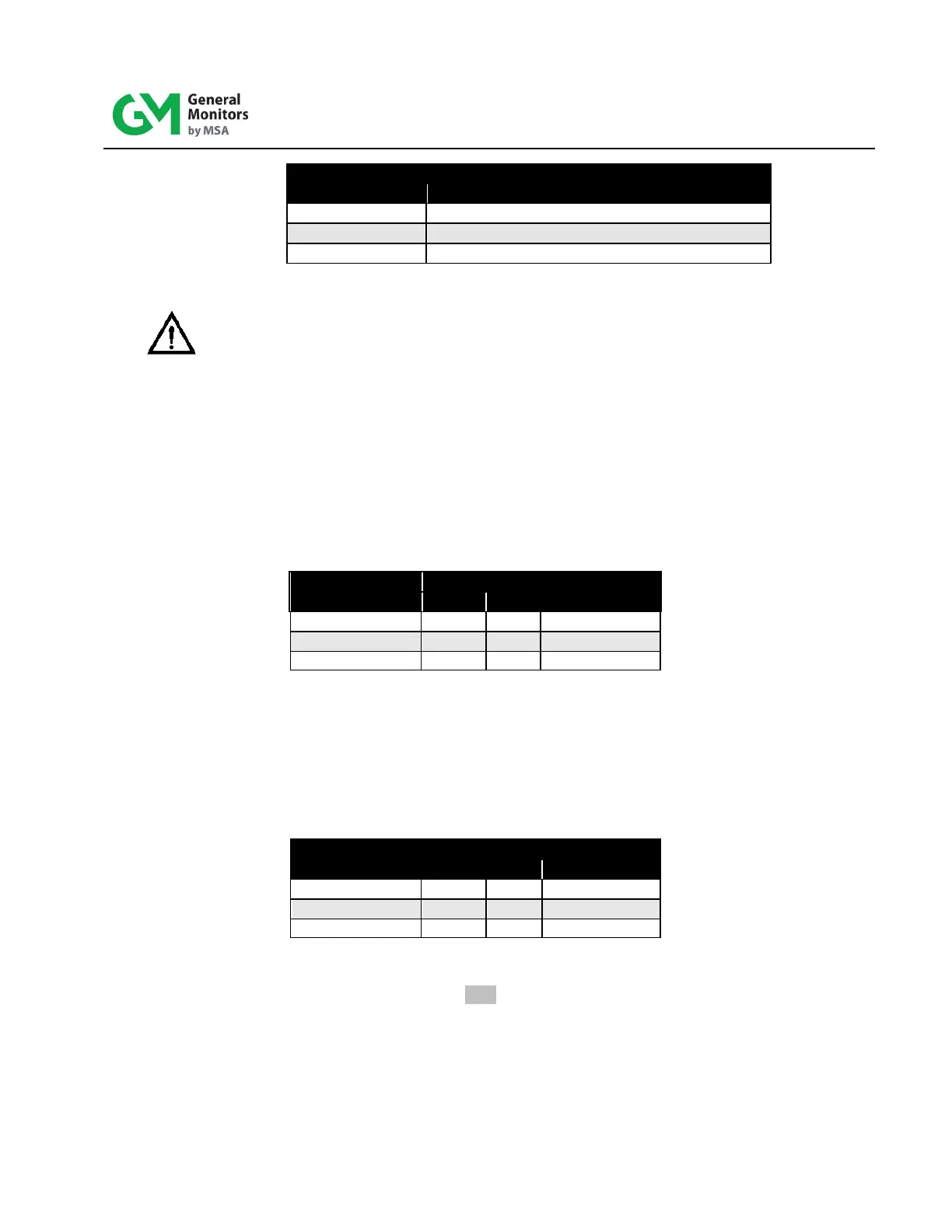
ALARM RELAY
Table 5: De-Energized Alarm Relay Contacts
The above chart shows the high and low alarm contacts in the st andard de-energized
state (with power applied). These two alarm relays are normally de-energized unless
specially ordered for normally energized operation. The fault relay is always sup pli ed
normally energized.
If normally energized, the terminations are:
ALARM RELAY
Table 6: Energized Alarm Relay Terminations
For more information, see Section 7.10.