16
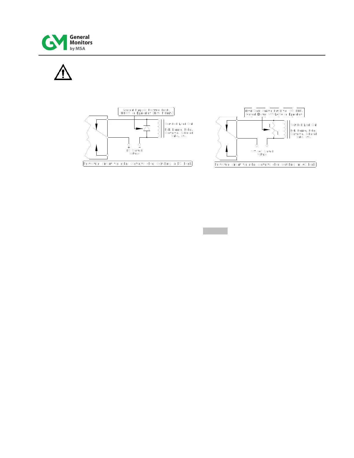
CAUTION: Inductive loads, such as bells, buzzers, relays, contactors, solenoi d valves,
etc., connected to the High alarm, Low alarm and Fault alarm relays must be
clamped down as shown in the diagrams below. Unclamped inductive l oads
can generate voltage spikes in excess of 1000 Volts. Spikes of this
magnitude will cause false alarms and possible damage.
Figure 7: Protection Circuit for Relay Contacts
2.9 Special Voting Option
If the special voting option has been ordered f or eight channels or more, special
interconnections must be made between the Model 610A Controllers. Terminals for these
interconnections are on terminal block TB2, which is the set of terminal b loc ks loc at ed
horizontally along the bottom of the controller (Figure 11).
The terminals to be interconnected are identified as follows and are l o cat ed within the
area labeled “VOTING”:
“ - “
“ H ”
“ L ”
“ M ”
“ V ”
Use AWG 18 to AWG 20 cable and connect these terminals to the like terminals on t he
second Model 610A Controller.
If 12 or 16 channels are to be in the zone, continue the same interconnect ion between
the second and third controller and between the third and fourth.