18
3.0 Start-Up and Operation
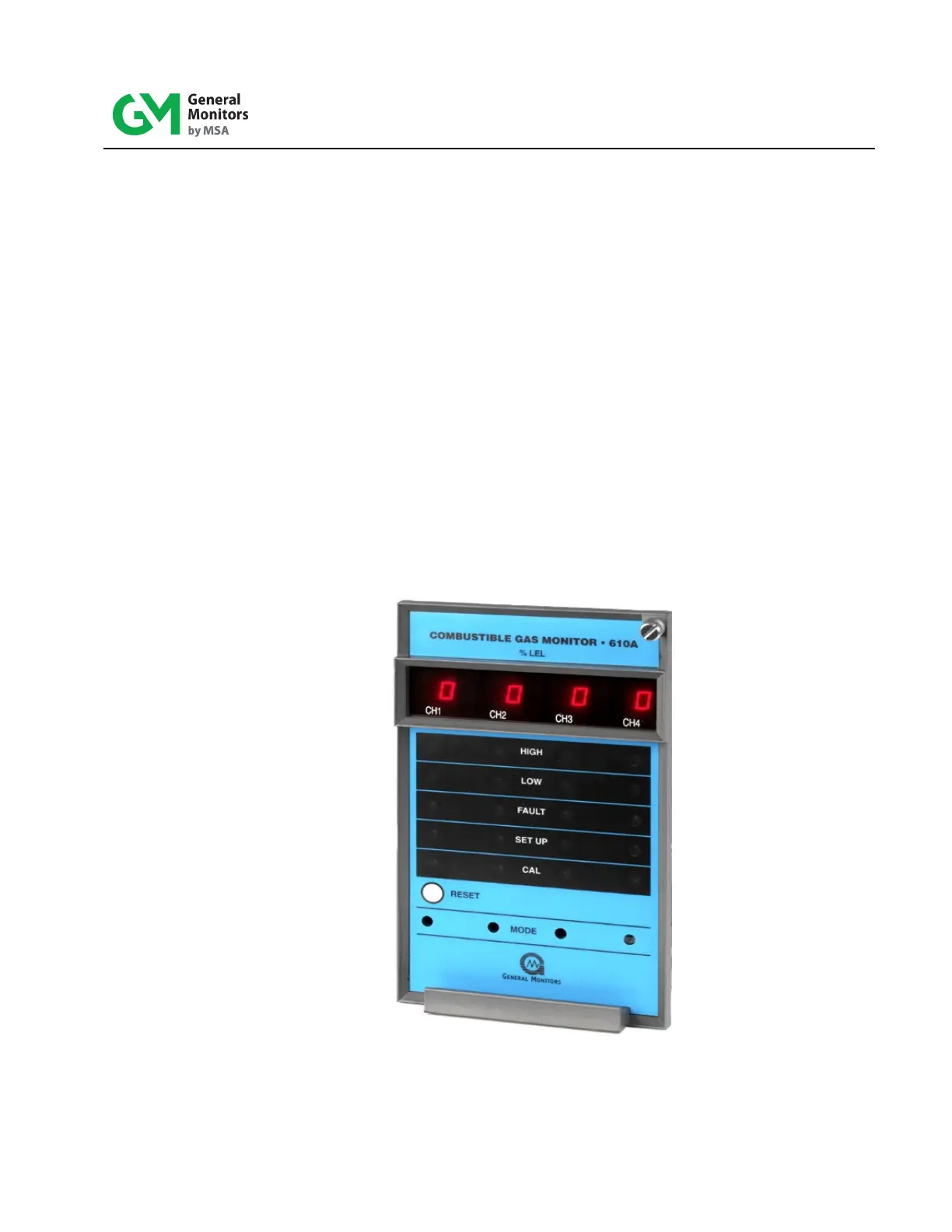
3.1 Types of User Interfaces
User interf aces are provided so that the operator may interpret and direct the Model 610A
in the performance of its various functions. User interfaces consist of a di gi tal d is play ,
status indicators, a mode button and a reset button.
• The digital display provides the user with the gas concentration at the sensor
site, fault diagnostic codes, calibration prompts, and setup parameters.
• The status indicators provide the user with an indication of the current m ode of
operation: HI GH (high alarm), LOW (low alarm), FAULT (fault alarm), SETUP
(setup and setup check modes), and CAL (calibration or calibration check
modes).
• Mode button provides the user access to the Calibrat ion, Calibrat ion Chec k,
Setup and Setup Check modes. The Mode button is located behind the front
panel and is accessed using a small screwdriver in the front of the unit.
• The Reset button allows the user to reset latched alarms.
Figure 8: Front Panel Display