27
bef ore the High alarm relay will actuate. All other functions of the Model 610A Control l er
will be the same as for the non-voting system.
If two f our-channel units are to be employed to monitor one zone, the second Model
610A Controller can be interconnected to the first unit. The Hi g h alarm relays in bot h
Model 610A Controllers will actuate when any two or more of the eight channels reach
the alarm set point. The Low and Fault relays will function the same as t hey do in non-
voting systems (16 channel).
A maximum of four (4) Model 610A Controllers can be employed in t his vot ing o ption.
(Please ref er to Section 7. 10, for typical interconnections).
NOTE: When more than one Model 610A Controller is used in a zone, all of the
controllers must be mounted adjacent to one another, to keep the
interconnecting leads as short as possible.
The Reset button for canceling latched alarm circuits is located on the front panel. The
circuits will only reset if the gas concentration has fallen below the set point level.
3.10.2 Set Up Options
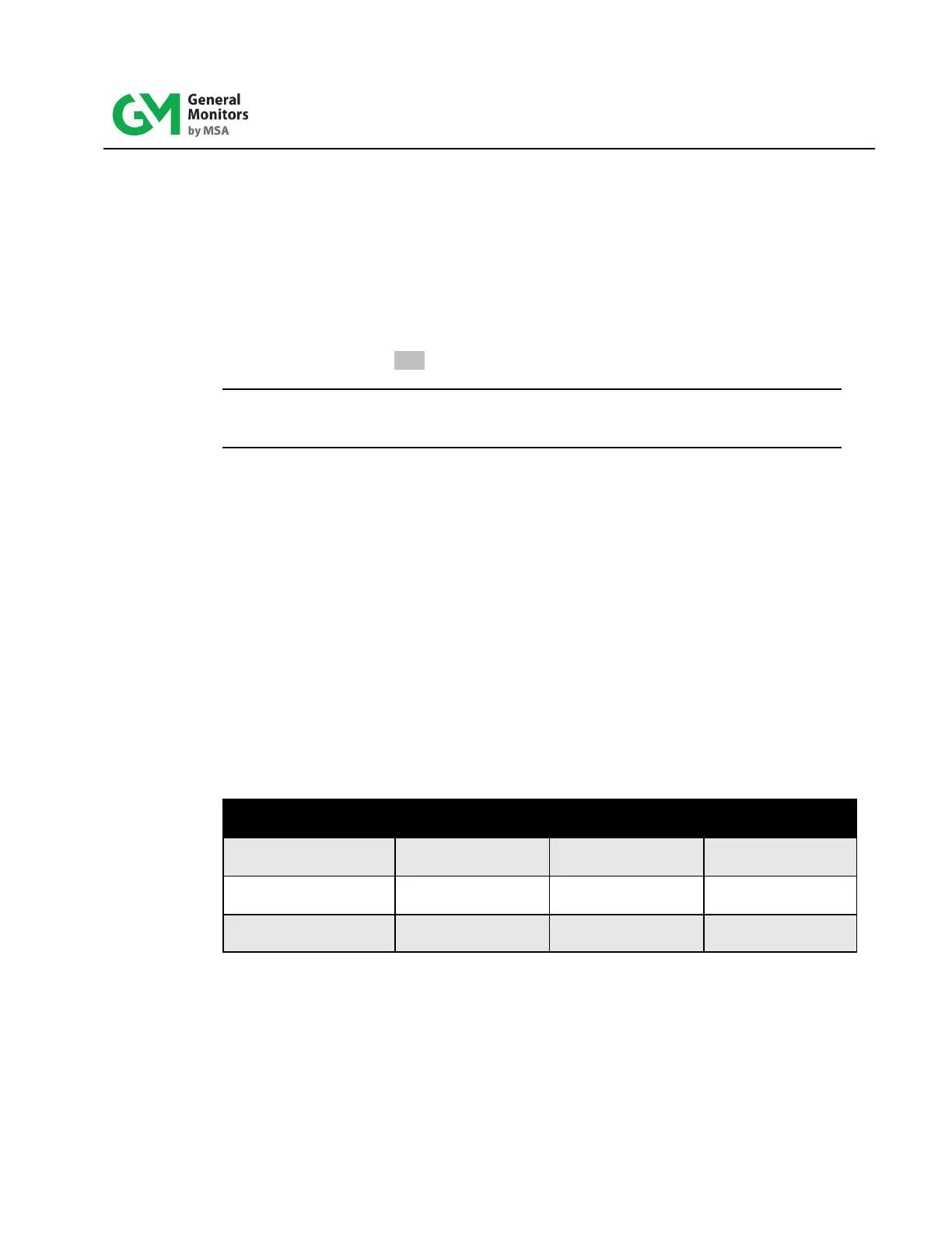
There are purchasable configured options of the Model 610A. The f ollowing list and table
outlines those options:
• Common Relays: The Master Board contains one set of relays f or all four
channels.
• Common Alarms: Alarm set points can be set on the Master Board and is
common on all four boards.
• Discrete Relays: Each board has its own set of relays.
• Discrete Alarms: Alarm set points can be set on each channel separately.
Common Relays /
Common Alarms
Discrete Relays /
Common Alarms
Discrete Relays /
Discrete Alarms
Enabled only on
Master board
Enabled only on
Master board
Enabled only on
Master board
Enabled only on
Master board
Table 8: Relay Alarm Options