2-10
Unit Power Wiring
A separate, dedicated power source is recommended for the refrigerant
monitor to ensure that the unit remains powered when other circuits are
shut down for servicing, routine maintenance or shift changes.
The mo
nitor uses a wide range power supply which can accept AC
power from 100 to 240 volts, 50 or 60 Hz. The power wiring should
enter the unit through one of the openings on the right side of the
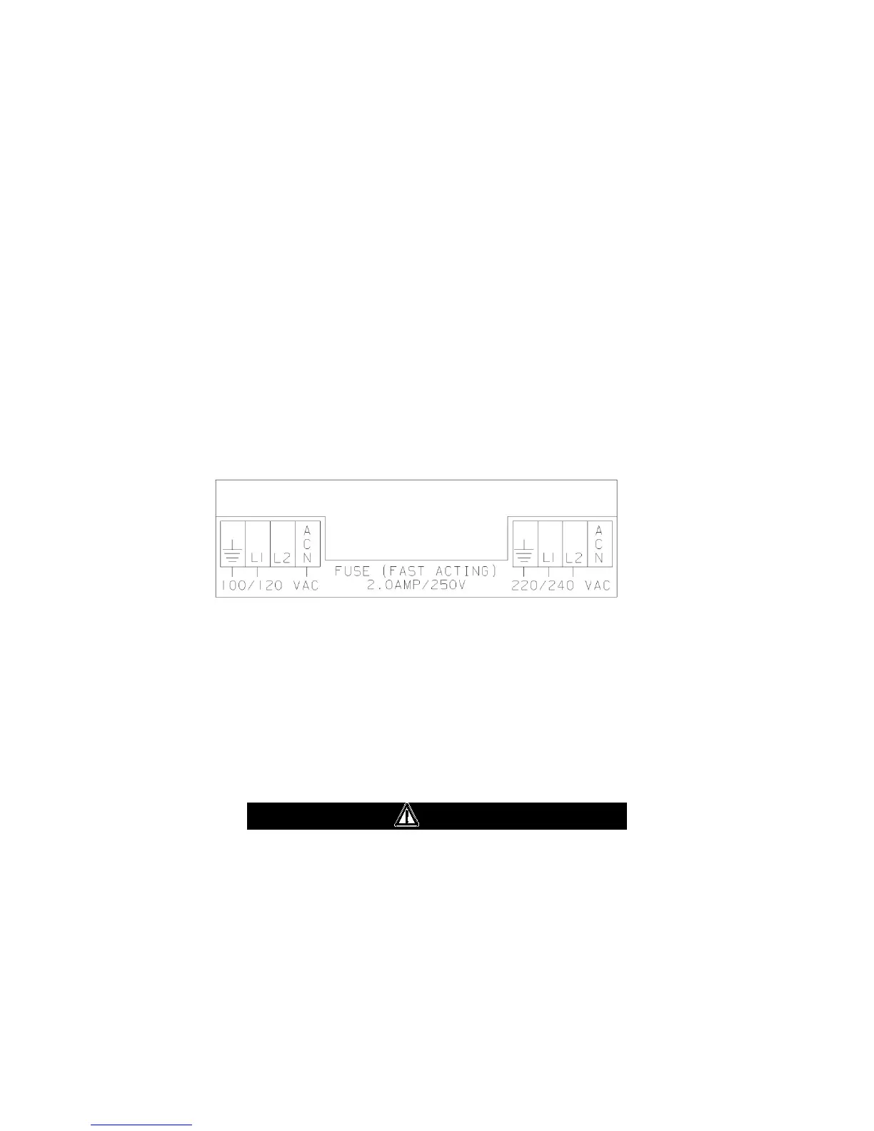
enclosure. Connections are made to the screw terminals labeled L1, L2,
ACN and GND, located in the upper right side of the unit (FIGURE 2-4).
The maximum wire size that these connectors can accept is #12 AWG.
The i
ncoming power provided to the monitor determines the
configuration of the fuse(s) and wiring to the main power terminal block.
FIGURE 2-4 shows the fuse and wire connections for various voltages.
Fi
gure 2-4. Primary Power Wiring
Power Supply Wiring
1.
Using a screwdriver, loosen the two latches on the enclosure door
(FIGURE 2-1).
2.
Open the front door.
3.
Determine the power requirements for your Chillgard RT unit,
ensuring the power i
s clean and reliable. (Refer to TABLE 1-1 for
current capa
city specifications.)
CAUTION
If unsure of your power available, contact your facility
engineer or safety officer. If incorrect power is applied,
damage may occur to the instrument.