Figure 13 Highlighted areas show where to press when replacing a board stack.
NOTICE
• AvoidpressingontheleftandrightareaswheretheLEDsarelocated.Pressingdirectlyonthedisplaywilldamagethe
displayandwillvoidthewarranty.
• Ensurethattheelectronicsassemblyisfullyengagedinthemountingholes.Ifnotfullyseated,theuserinterface
buttonsmaynotfunctionproperly.
9. Replacethecoverbyturningclockwise.
10.Tightenthesetscrewlocatedonthelidusinga1.5mmAllenwrench.
3.4.5 IntegratedMountingPoints
TheULTIMAX5000transmittercanbesurfacemountedwithoutanyadditionalbracketsusingtheintegratedmountingtabs.
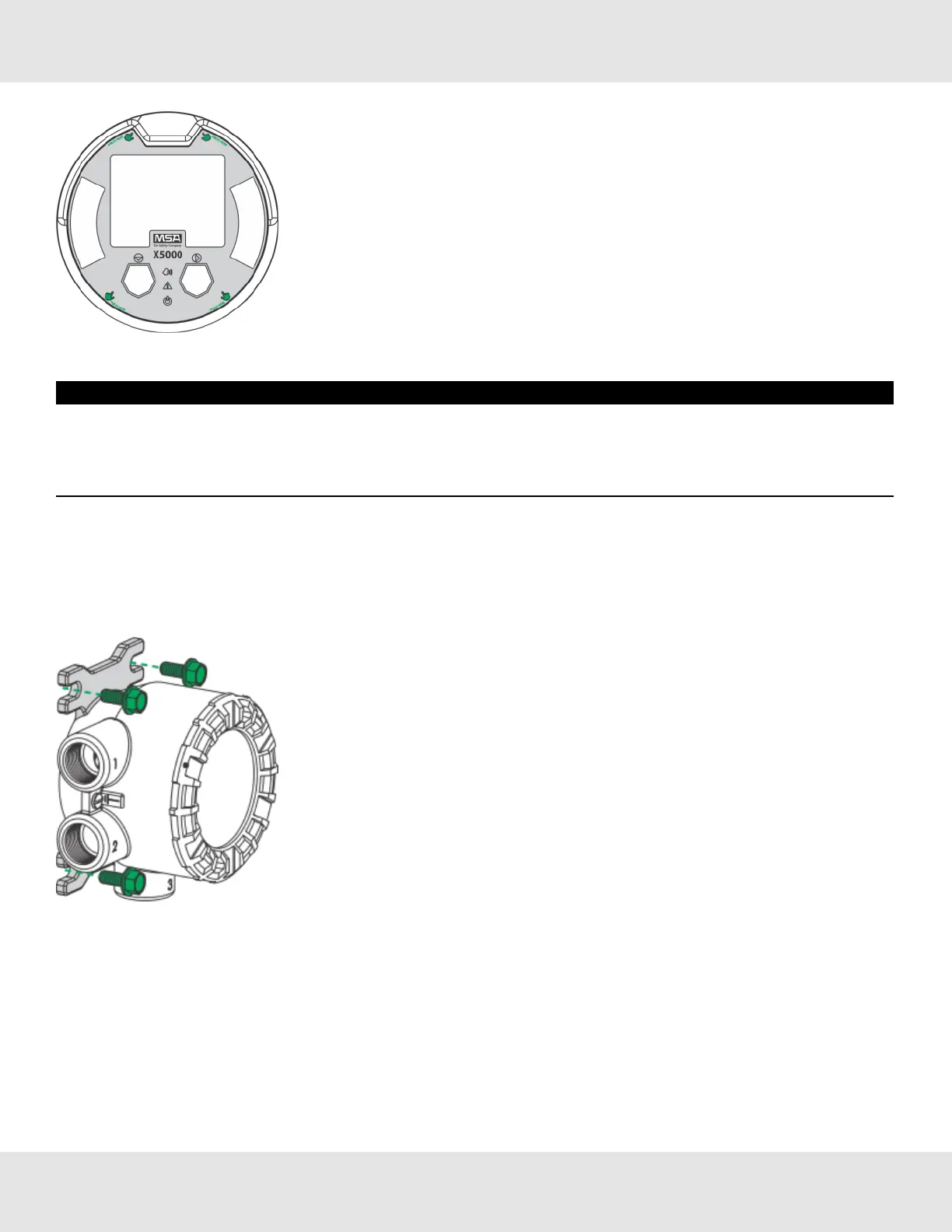
Figure 14 Internal Mounting Tabs (not compatible with ULTIMA XIR PLUS Sensors)
AnsupplementarymountingbracketisrequiredforsurfacemountingtheULTIMAX5000withanattachedULTIMA
XIRPLUSsensor.
17 Ultima X5000 Gas Monitor US
3 Installation