2-23
Hardware Setup
PIN SIGNAL DESCRIPTION PIN SIGNAL DESCRIPTION
1 VCC5 VCC 5V 2 VDD3 VDD 3.3V
3 SPDFO S/PDIF output 4 (No Pin) Key
5 GND Ground 6 SPDFI S/PDIF input
7 LFE-OUT Audio bass output 8 SOUT-R Audio right surrounding output
9 CET-OUT Audio center output 10 SOUT-L Audio left surrounding output
11 GND Ground 12 GND Ground
JSP1 Pin Definition
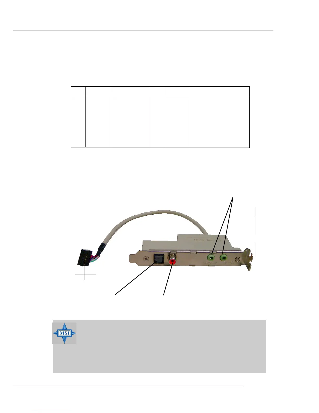
Optional S-Bracket
SPDIF jack (optical)
SPDIF jack (coaxial)
Analog Line-Out jack
Connect to JSP1
MSI Reminds You...
Before connecting to the S-Bracket, be sure to remove the JS1
jumpers (see p.2-32 for details) and power off the system first, then
you are able to attach your S-Bracket to the JSP1 connector. Your
mainboard may be damaged seriously if not following the
instruction above.
 Loading...