THE FUEL SYSTEM AND GOVERNOR
35
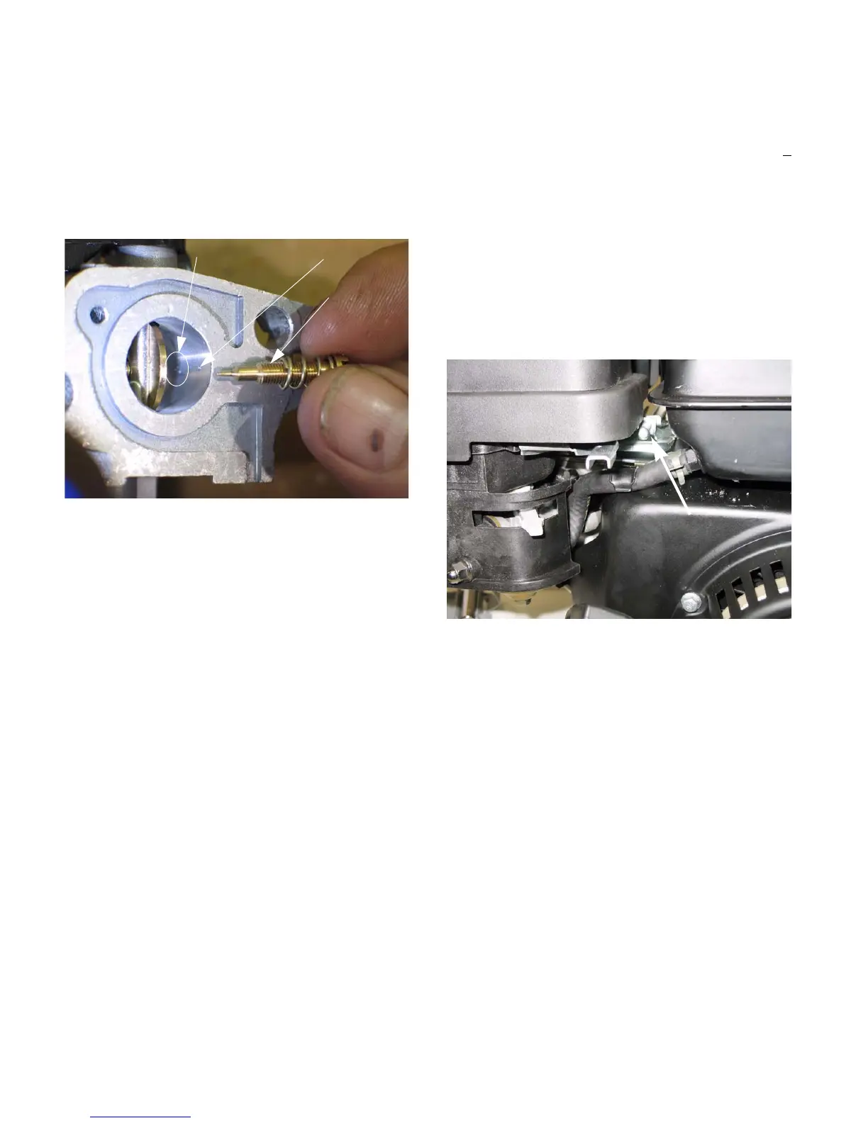
NOTE: The pilot screw regulates how much of
this pre-mixed fuel/air emulsion is allowed to
enter the throat of the carburetor, to atomize
down-stream of the throttle plate. On current
production units it is set at the factory and the
screw head is removed.
See Figure 4.23.
NOTE: The transition ports are fixed. They are
drilled into the throat of the carburetor, down-
stream of the venturi. They lie behind the brass
welch plug near the pilot screw.
10. Soak the Carburetor body in a suitable solvent
until clean.
11. Rinse it thoroughly.
12. Dry the carburetor body using compressed air.
13. Reassembly the carburetor and install it by fol-
lowing steps 1-8 in reverse order.
14. Start engine and check the idle RPM using a
tachometer.
NOTE: Idle speed: If applicable, is 1,800 RPM +
160 RPM, set using throttle stop screw.
15. Check the top no load speed of the engine.
NOTE: The top no load speed will vary depend-
ing on the application. The specification for it will
be listed in the manual for each application.
16. The top no-load speed is easily adjusted by
tightening/loosing the speed adjustment screw.
Tighten the screw to decrease speed and loosen
it to increase speed..
See Figure 4.24.
Figure 4.23
Transition ports Pilot port
Pilot screw
(before head
is removed)
Figure 4.24
Adjustment screw
www.mymowerparts.com
For Discount White Outdoor Parts Call 606-678-9623 or 606-561-4983
 Loading...


