IGNITION SYSTEM
55
Installing the module and setting the air gap
NOTE: If just setting the air gap, loosen the
module mounting screws first then follow the
same steps as described below.
1. Rotate the flywheel so that the magnets are
away from where the module is mounted.
2. Install the module. Do not tighten the module
down.
3. Place a non-ferrous feeler gauge between the
module and the flywheel.
NOTE: The air gap should be .008”-.016” (.2-
.4mm).
4. Rotate the flywheel so that the magnets align
with the legs of the module while holding the
feeler gauge in place.
See Figure 7.14.
5. Tighten the module mounting screws to a torque
of 80 - 106 in-lbs (9 - 12 Nm).
6. Rotate the flywheel to remove the feeler gauge.
7. Install the blower housing and starter.
8. Hook the spark plug wire from the clip in the car-
buretor insulator.
9. Install the Heatbox (snow engines) and intake
elbow by following the steps described in Chap
-
ter 3: Air Intake Systems.
10. Connect the spark plug wire to the spark plug.
11. Test run the engine before returning to service.
Flywheel
The flywheel holds the magnets that induce a field in
the module which in turn produces a spark. But it also
controls the timing of the ignition system by controlling
when the magnets are introduced to the module.
A sheared flywheel key will throw off the ignition timing.
They are uncommon on the MTD engine. If one is
found, check for a bent crankshaft. To Remove and/or
inspect the flywheel and key:
1. Remove the recoil assembly by following the
steps describe in Chapter 6: Starter and Charg
-
ing System.
2. Remove the blower housing.
3. Loosen the flywheel nut until it is a couple of
threads past the end of the crankshaft using a
19mm wrench.
4. Remove the flywheel by applying a sharp blow
to the crankshaft using a brass drift punch and a
hammer while gently prying with a prybar. The
flywheel will loosen then lift it off.
NOTE: Never strike the crankshaft directly with a
hammer. To prevent damage to the crankshaft
use a brass drift punch or a piece of wood
between the hammer and the crankshaft.
See Figure 7.15.
CAUTION: If the flywheel shows any signs of
physical damage such as cracks, broken vanes,
or damaged key-way, replace it. A damaged fly
-
wheel poses a threat of burst failure. Burst fail-
ures are extremely hazardous to surrounding
people and property.
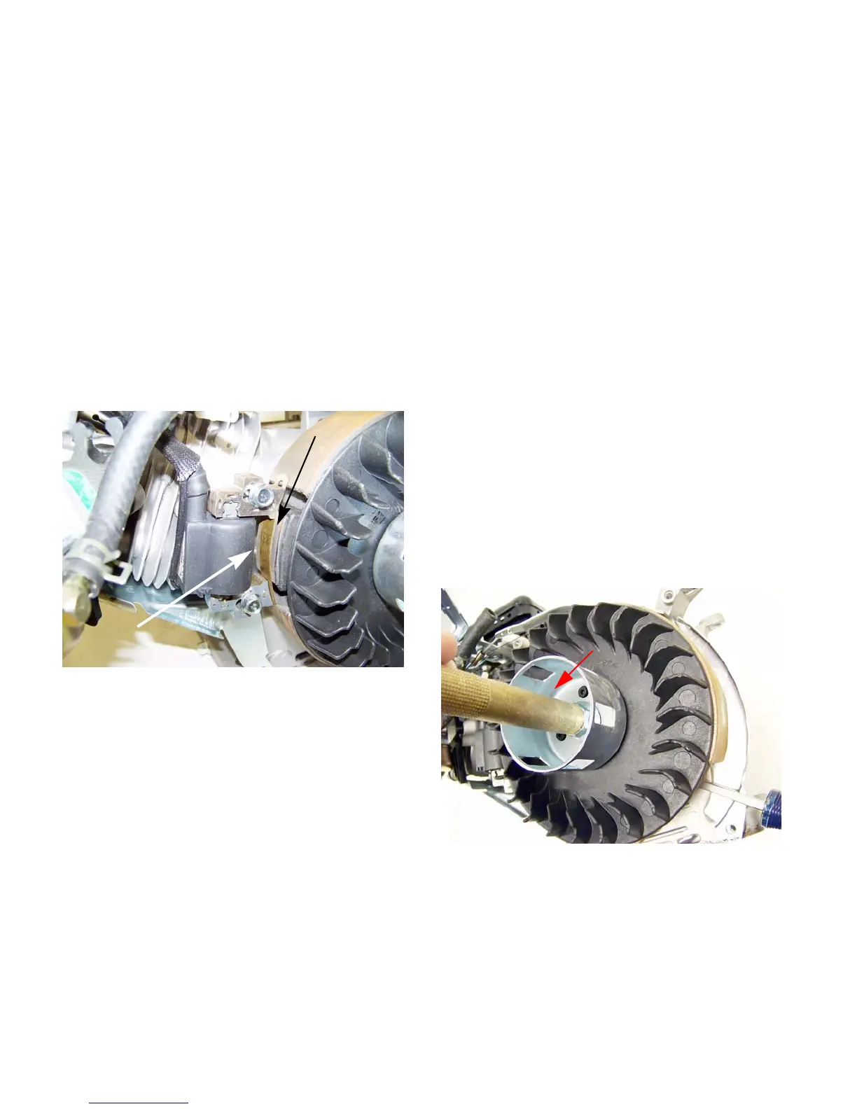
Figure 7.14
Magnet
.010” feeler
gauge
Figure 7.15
Brass Drift
punch
www.mymowerparts.com
For Discount White Outdoor Parts Call 606-678-9623 or 606-561-4983
 Loading...


