THE FUEL SYSTEM AND GOVERNOR
36
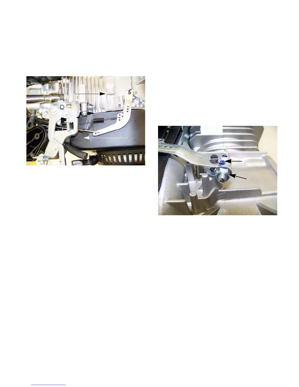
Governor
The engine speed is controlled by a balance between
the force applied by a spring (pulling the throttle open)
and a flyweight mechanism within the engine applying
force to the governor arm (pushing the throttle closed).
See Figure 4.25.
NOTE: While the mechanism is simple and
robust, it is important to pay attention when
working on parts near the governor. Binding
caused by interference with mis-routed lines or
cables may make the governor unresponsive.
NOTE: When a governed engine “hunts”, it is
generally an indication of a lean fuel/air mixture,
rather than a problem with the governor.
Figure 4.25
Spring tension
Governor action
Governor arm
To remove the governor arm from the governor shaft:
1. Remove the fuel tank by following the steps
described in the Fuel Tank section of this chap
-
ter.
2. Unhook the governor spring.
NOTE: Mark which hole the spring was in to
ensure it goes back in the same hole.
3. Unhook the governor linage and throttle return
spring.
4. Loosen the nut and through bolt. See Figure
4.26.
5. Carefully spread open the seam on the arm.
6. Carefully slide the Governor arm off of the gov-
ernor shaft.
7. Install the governor arm by rotating the governor
shaft clockwise until it stops.
8. Slide the arm onto the shaft. The flat on the top
of the shaft should be roughly perpendicular to
the arm.
See Figure 4.26.
NOTE: There is a hairpin clip that keeps the gov-
ernor shaft from sliding into the engine. It may be
necessary to hold the shaft while sliding the arm
on to prevent it from going into the engine.
9. Tighten the nut on the clamp bolt to secure the
arm.
10. Attach the governor linkage and spring.
11. Adjust the governor to maintain top no-load
speed as described in a previous section of this
chapter.
Figure 4.26
Loosen nut
Spread here
www.mymowerparts.com
For Discount White Outdoor Parts Call 606-678-9623 or 606-561-4983
 Loading...


