STARTER AND CHARGING SYSTEMS
49
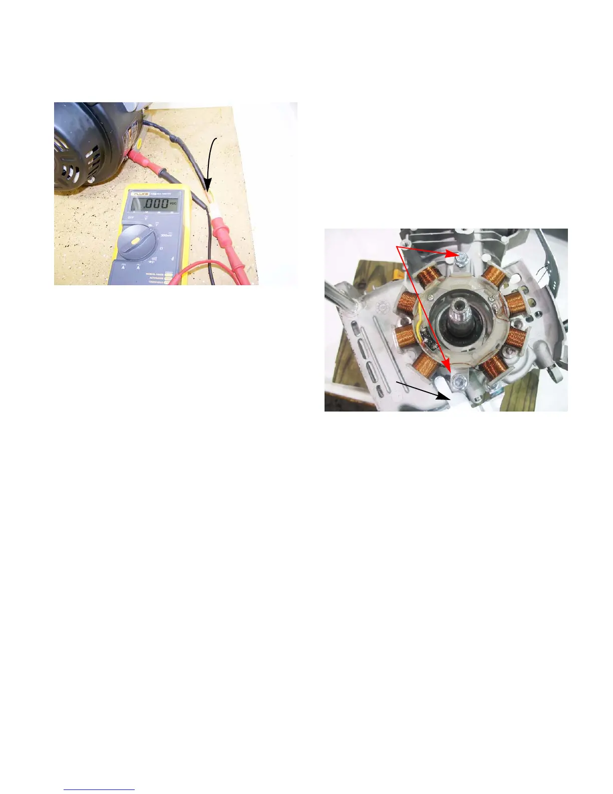
8. Move the red (+) to the red wire of the charger
harness.
See Figure 6.15.
9. The multimeter should read 17 - 26Vdc.
10. If the results do not match what is listed above,
replace the stator.
Figure 6.15
Red wire
Stator
To remove/replace the stator:
1. Remove and ground the spark plug wire.
2. Remove the flywheel by following the steps
described in Chapter 7: Ignition System.
3. Remove the baffle that covers the charger har-
ness using a 10mm wrench.
4. Remove the two screws that secures the stator
with a 10mm wrench and lift the stator off of the
engine.
See Figure 6.16.
5. Install the stator by following the above steps in
reverse order.
6. Test run the engine in a safe area and retest the
voltage output before returning to service.
Rotor
Rotor failures are extremely rare. To check the rotor:
• Confirm that the magnets are firmly attached to
the flywheel.
• Hold a screwdriver or a similar tool made of fer-
rous metal within a 1/4” of each magnet.
• If the tool is drawn to the magnet, the rotor is
good.
Figure 6.16
Remove these
Baffle
screws
www.mymowerparts.com
For Discount White Outdoor Parts Call 606-678-9623 or 606-561-4983
 Loading...


