STARTER AND CHARGING SYSTEMS
48
Charging system
Description
Some engines are equipped with a charging system.
The charging system consists of:
• Alternator stator: copper field windings around
an iron core. The stator is attached to the engine
block beneath the flywheel.
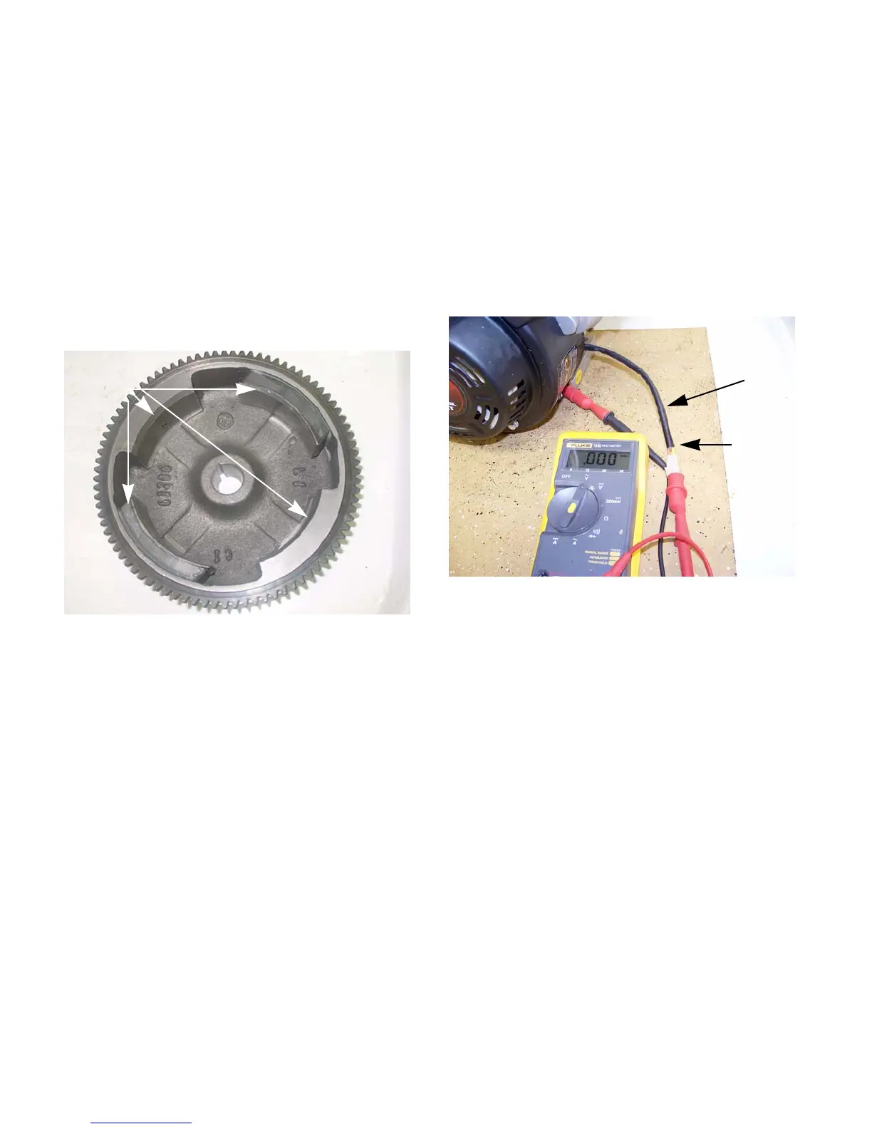
• Four magnets on the inside of the flywheel, refer
to figure 6.13, that rotate around a stator that is
mounted to the cylinder block. As the crankshaft
and flywheel rotate, the moving magnets induce
a charge in the stator.
• A rectifier: A set of diodes that turn the AC cur-
rent into DC current.
Testing
The charging system will produce AC and DC voltages.
The rectifier for the DC voltage is inside of the stator
and is not serviceable. To test the charging system:
1. Disconnect the charger harness.
2. Connect the black (-) lead of a digital multimeter
to a good ground on the engine.
3. Connect the red (+) lead of the multimeter to the
yellow wire in the charger harness.
See Figure
6.14.
4. Set the multimeter to read AC voltage.
5. Start the engine and run it at full throttle.
6. The multimeter should read a voltage of 13 -
18Vac.
7. Set the multimeter read DC voltage.
Figure 6.13
Magnets
Figure 6.14
Charger harness
Yellow wire
www.mymowerparts.com
For Discount White Outdoor Parts Call 606-678-9623 or 606-561-4983
 Loading...


