IGNITION SYSTEM
53
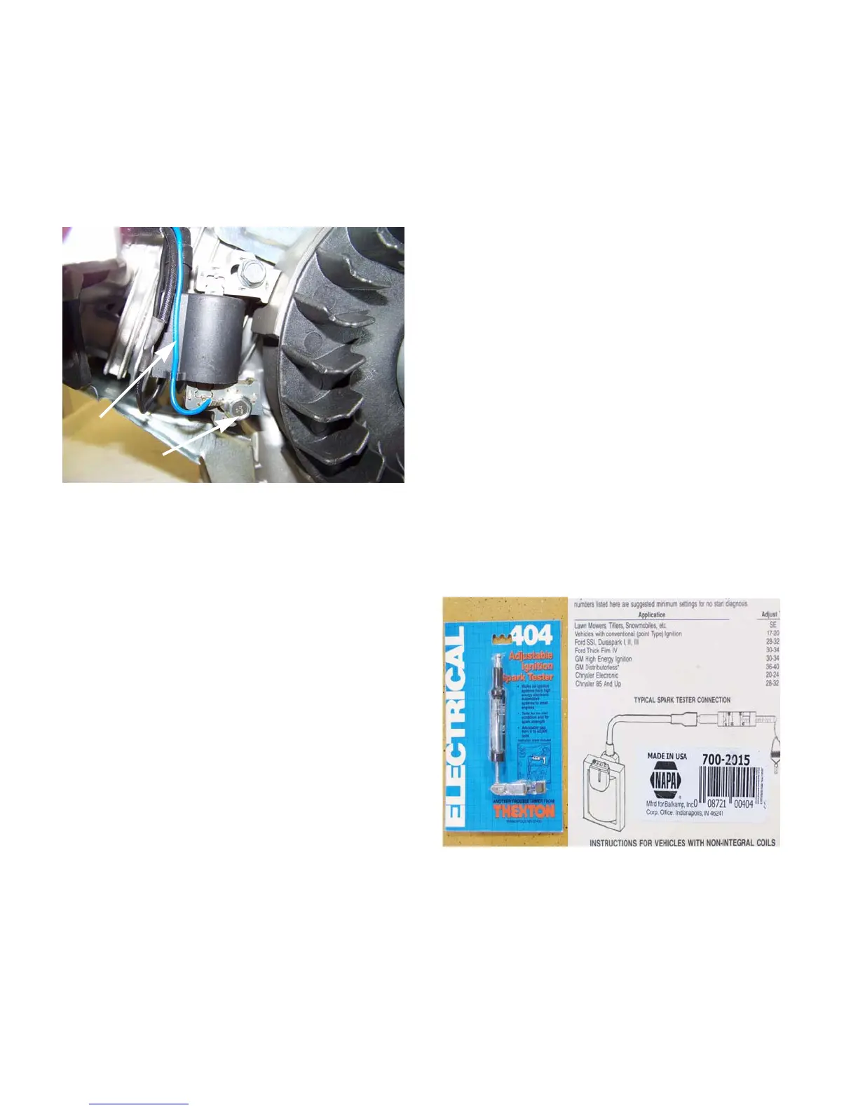
8. Set the multimeter to the ohms (Ω) scale.
• If the multimeter shows continuity, replace the
module.
• If the multimeter does not show continuity,
check the wire for a break and check the ground
connection. See Figure 7.9.
The module
The coil in this ignition system is an inductive discharge
magneto, contained in a single module.
• The inductive discharge magneto has a two leg
design.
• The magneto is energized by the passing of a
pair of magnets mounted in the flywheel.
• Ignition timing is set by the location of the fly-
wheel in relation to the crankshaft. Proper timing
is maintained by a steel key.
Normal performance of the coil is to produce at least
10,000 volts at starter-rope pull-through speed.
The presence or absence of strong spark, with the stop
switch known to be good, is generally enough to iden-
tify the ignition coil as good or bad. Resistance read-
ings may help confirm the source of the failure, but are
generally meaningless because they only measure a
small part of the module.
NOTE: Presence of a weak spark maybe the
result of an improper air gap. The air gap space
should be .008”-.016” (.2-.4mm).
Simple spark-testers are readily available and inexpen-
sive. Thexton Part # 404 is available from a variety of
retailers, and similar units are available form other
manufacturers. See Figure 7.10.
NOTE: If the complaint is that the engine quits
running when it gets warm, the ignition module
should be tested with the engine at normal oper
-
ating temperature.
Figure 7.9
Blue wire
Ground connection
Figure 7.10
Instructions on
back of package
www.mymowerparts.com
For Discount White Outdoor Parts Call 606-678-9623 or 606-561-4983
 Loading...


