STARTER AND CHARGING SYSTEMS
46
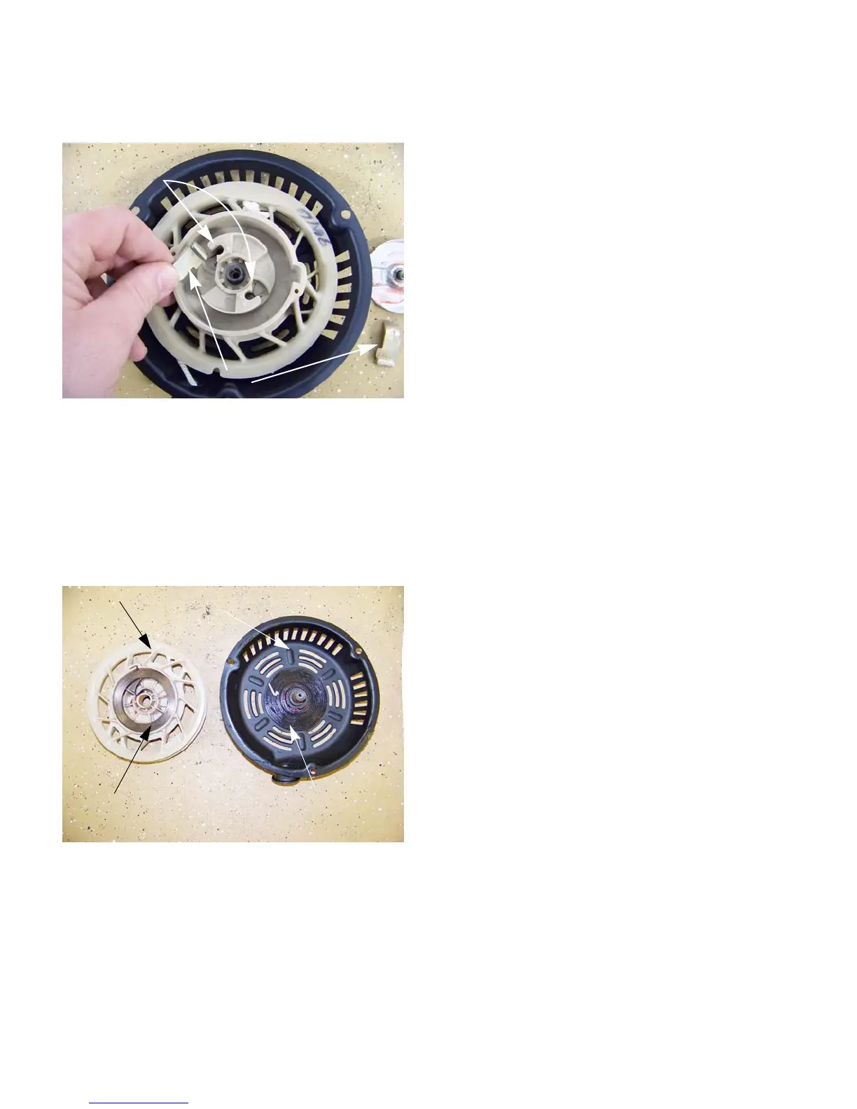
4. Inspect the pawls and torsion springs for wear
and damage.
See Figure 6.8.
5. Carefully lift the spring and pulley out of the
recoil housing.
See Figure 6.9.
CAUTION: The recoil spring is under tension
and can release as the pulley is removed.
CAUTION: Eye protection should be worn while
removing the starter pulley.
NOTE: If the spring is undamaged, but has been
removed from the pulley, the spring may be re-
wound. Hook the end of the spring into the slot in
the outer lip of the recess of the pulley and wind
the spring into the recess in a counter-clockwise
direction.
NOTE: Evaluate the damage, including parts
prices and local labor rates. In some parts of the
country, it makes economic sense to replace the
complete assembly, in other areas labor rates
favor repair.
6. To re-assemble, apply a small amount of lithium-
based chassis grease to the surface of the recoil
housing that contacts the spring.
NOTE: Use low temperature grease on the snow
engines.
7. Carefully position the pulley and spring in the
recoil housing. Rotate the pulley gently counter-
clockwise until the spring seats, allowing the pul
-
ley to fall into position.
8. Install the torsion springs and pawls so that the
long arm of the spring reaches outside of the
pawl, and draws it toward the center of the
assembly.
See Figure 6.8.
NOTE: The rolled end of the pawl fits in the
recess in the starter pulley. The hooked end
engages the starter cup. The roll faces inward
and the hook faces outward.
NOTE: The extrusions on the pressure plate
should fall inside of the pawls as the starter is
assembled.
NOTE: Drag on the pressure plate, from the fric-
tion between the compression spring and the
head of the shoulder screw causes these extru
-
sions to force the pawls outward, engaging the
starter cup.
9. Apply a small amount of thread locking com-
pound such as Loctite 242 (blue) to the threads
of the shoulder screw, and install the screw.
Tighten it to a torque of 71 - 89 in-lb. (8 - 10 Nm).
10. Install the starter rope by following the steps
described in the previous section of this chapter.
11. Install the starter and tighten the starter nuts to a
torque of 53 - 71 in-lbs (6-8 Nm).
Figure 6.8
Torsion springs
Pawls
Figure 6.9
Pulley
Spring
Housing
Lithium grease
www.mymowerparts.com
For Discount White Outdoor Parts Call 606-678-9623 or 606-561-4983
 Loading...


