2
About the job computer
System overview
ECU-Midi job computer
Junction box
ISOBUS cable
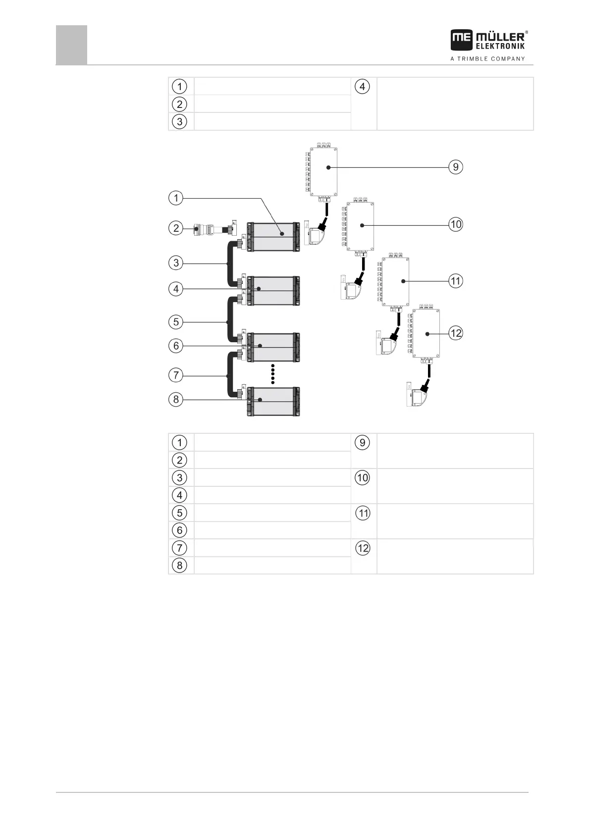
Large system with 4 job computers, max. 7 job computers are possible
1. ECU-Midi job computer
Junction box 1st Job computer
ISOBUS cable
Connecting cable between the job computers
Junction box 2nd Job computer
2. ECU-Midi job computer
Connecting cable between the job computers
Junction box 3rd Job computer
3. ECU-Midi job computer
Connecting cable between the job computers
Junction box 4th Job computer
4th ECU-Midi job computer
Each job computer is responsible for controlling selected functions of the slurry tanker and receives
signals from selected sensors. For systems with multiple job computers, identical job computers and
junction boxes are used respectively.
In the slurry tanker configurator, you can see which sensors and actuators can be connected to the
junction box.
Example
The following diagram shows an example of how an implement can be structured:
 Loading...