Copyright © 2010 Intermatic, Inc.
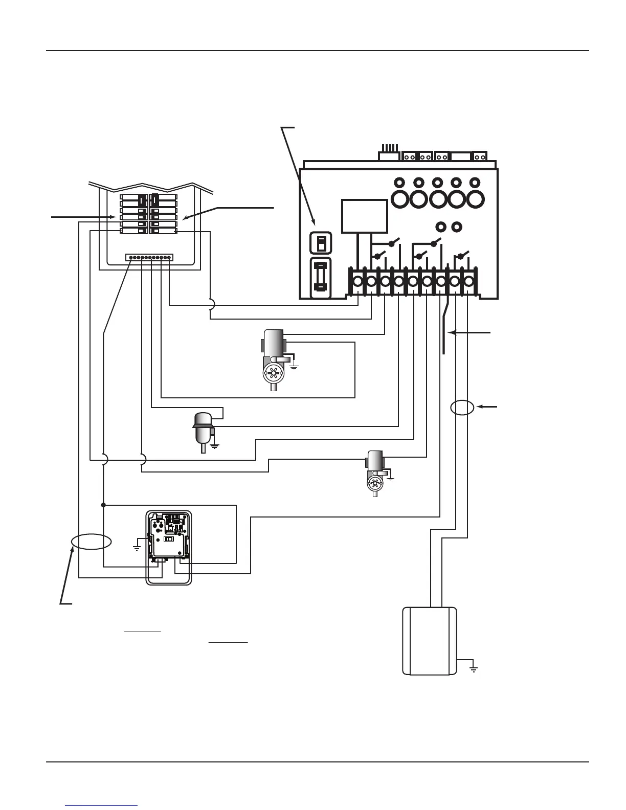
1-pole Breaker
1-pole
Breakers
15 A. Max.
NEUTRAL BUS
Select Breaker to match wire size
and load requirement. Observe
maximum control circuit capacity.
Heater Enable Circuit
(24 VAC Typical) MUST
connect to Terminals 8 & 9
on PE653 and to Fireman’s
Switch on the Heater
Actuator model P4243ME must be installed in a
separate enclosure. Intermatic model 2T2485GA
is recommended. Refer to Actuator installation
instructions for additional wiring instructions.
NOTE:
Refer to Heater manufacturer’s
installation instructions for
Heater installation and setup
NOTE:
Low Voltage
Divider provided
must be installed
for Heater circuit.
NOTE:
The combined load on Terminals 6 & 7
must NOT exceed 15 amps Resistive.
120 VAC
Blower
120 VAC
Actuator Control
120 VAC
1-Speed
Pump
120 VAC
Booster
Pump
HOT
NEUTRAL
120 VAC Actuator Power
NOTE:
Wires must exit
through separate
opening from line
voltage wires. Use
shutter bushing
provided.
BLK
BLK/WHT
BLK/WHT
WHITE
HEATER
# 1 Button
# 2 Button
# 1 Button
# 3 Button
# 4 Button
# 5 Button
RELAY 1
VALVES
RELAY 2
1 2 3 4 5 6 7 8 9
RECEIVER
POWER
SUPPLY
120V
240V
1 2 3 4 5
Make sure that voltage selector switch is in 120V
position before applying power to Terminals 1 & 2