Copyright © 2010 Intermatic, Inc.
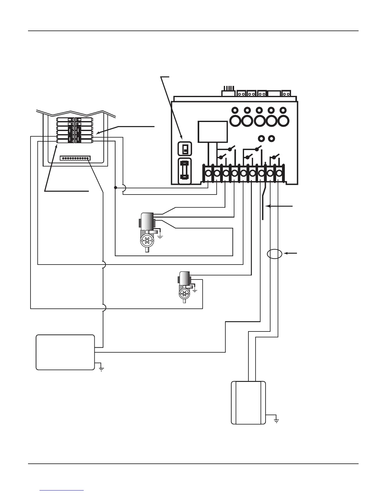
NEUTRAL BUS
1 2 3 4 5 6 7 8 9
RECEIVER
POWER
SUPPLY
120V
240V
1 2 3 4 5
LOW
2-pole Breaker
2-pole Breaker
15 A. Max.
Select Breaker to match wire size
and load requirement. Observe
maximum control circuit capacity.
Heater Enable Circuit
(24 VAC Typical) MUST
connect to Terminals 8 & 9
on PE653 and to Fireman’s
Switch on the Heater
NOTE:
Refer to Heater manufacturer’s
installation instructions for
Heater installation and setup
NOTE:
Low Voltage
Divider provided
must be installed
for Heater circuit.
NOTE:
The combined load on Terminals 6 & 7
must NOT exceed 15 amps Resistive.
240 VAC
Booster
240 VAC
2-Speed
Pump
HIGH
COMMON
NOTE:
Wires must exit
through separate
opening from line
voltage wires. Use
shutter bushing
provided.
HEATER
# 1 Button
# 2 Button
# 3 Button
# 5 Button
Make sure that voltage selector switch is in 240V
position before applying power to Terminals 1 & 2
Other 120 VAC
Equipment
# 4 Button