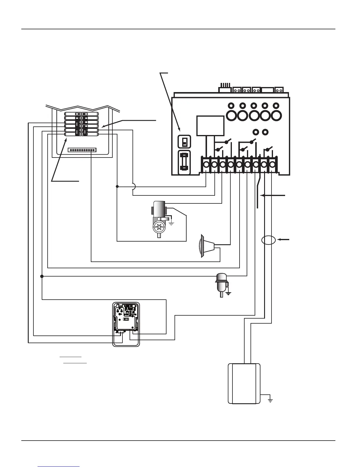
NEUTRAL BUS
2- pole
Breaker
2- pole
Breakers
Select Breaker to match wire size
and load requirement. Observe
maximum control circuit capacity.
240 VAC
1-Speed
Pump
L1
L2
# 1 Button
1 2 3 4 5 6 7 8 9
RECEIVER
POWER
SUPPLY
120V
240V
1 2 3 4 5
Heater Enable Circuit
(24 VAC Typical) MUST
connect to Terminals 8 & 9
on PE653 and to Fireman’s
Switch on the Heater
NOTE:
Refer to Heater manufacturer’s
installation instructions for
Heater installation and setup
NOTE:
Low Voltage
Divider provided
must be installed
for Heater circuit.
NOTE:
Wires must exit
through separate
opening from line
voltage wires. Use
shutter bushing
provided.
HEATER
# 5 Button
NOTE:
The combined load on Terminals 6 & 7
must NOT exceed 15 amps Resistive.
Actuator model P4243ME must be installed in a separate enclosure.
Intermatic model 2T2485GA is recommended. Refer to Actuator
installation instructions for additional wiring instructions.
240 VAC
Actuator Control
240 VAC Actuator Power
BLK
BLK/WHT
BLK/WHT
RED
# 4 Button
RELAY 1
VALVES
RELAY 2
Make sure that voltage selector switch is in 240V
position before applying power to Terminals 1 & 2
240 VAC
Blower
120VAC
Lights
# 2 Button
# 3 Button