36 Multi-Wave PE653-PE953 Installation Guide
Copyright © 2010 Intermatic, Inc.
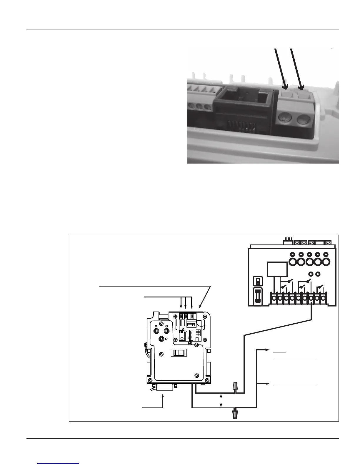
Communications to a
Variable-Speed Pump
If the Multi-Wave system includes a
variable-speed pump, you must wire
the pump’s communications cable
to the PE653 so the two devices can
communicate.
Connect one end of the control 1.
cable to the proper terminals on the
variable-speed pump. Refer to the
manufacturer’s instructions. The pump
manufacturer includes a cable with a
plug for the motor.
OBSERVE POLARITY. Connect the 2.
other two wires to the wiring block at
the far right of the top of the PE653. (Use the color code shown in Figure 3-4.)
Motorized Valve Actuator Connection and Synchronizing
The Multi-Wave Control System is capable of controlling Motorized Valve Actuators using Model
P4243ME Valve/Pump Switch Mechanism. When used, the P4243ME must be installed in an
enclosure that is separate from the PE653RC system. The P4243ME is prompted to position the 24 volt
motorized actuators when the P /S (Pool / Spa) button is pushed on the PE953 Hand Held Transmitter.
Figure 3-24
120 VAC Power:
Hot or L1 Black wire
Neutral White wire
240 VAC Power:
L1 Black wire
L2 Red wire
Power Leads are connected
directly to wires from the
transformer.
NOTE:
One Control wire for the P4243ME must
be connected to terminal 7 in the PE653.
Refer to wiring diagrams in Section 3.
NOTE:
Turn AC Power OFF to
both units BEFORE
making any wire
connections.
Drawing shown with Access Door removed.
Actuator Power connections:
Install polarized plug to connector.
3 connectors available.
Cable and connector supplied with
each PE24VA Actuator.
NOTE:
For 120V application: The
second Control wire for the
P4243ME must be connected
to Neutral.
For 240V application: The
second Control wire for the
P4243ME must be connected
to L2
Refer to wiring diagrams in
Section 3.
RELAY 1
VALVES
RELAY 2
Black & White
Black & White
Actuator Control Circuit
1 2 3 4 5 6 7 8 9
CONTROL
POWER
SUPPLY
120V
240V
1 2 3 4 5
Figure 3-25