User Manual
User Interface Introduction
1
3
21
18
6
7
9
13
14
20
23
5
19
2
4
15
11
4
8
22
22
10
12
17
16
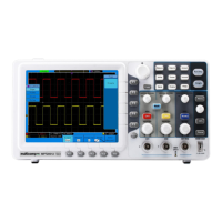
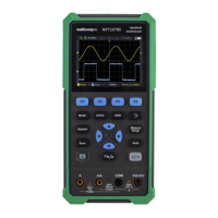
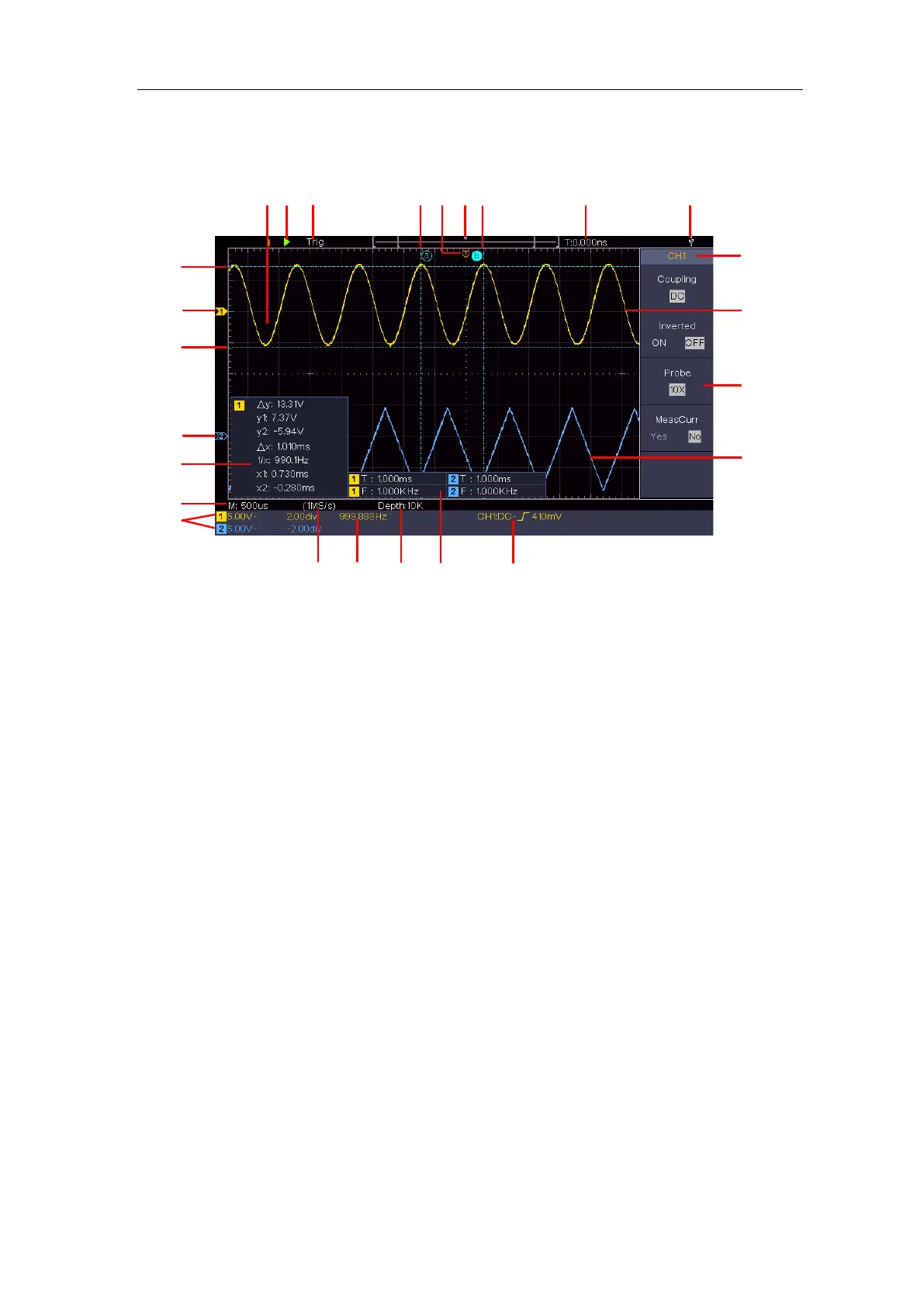
Figure 3-4 Illustrative Drawing of Display Interfaces
1. Waveform Display Area.
2. Run/Stop
3. The state of trigger, including:
Auto: Automatic mode and acquire waveform without triggering.
Trig: Trigger detected and acquire waveform.
Ready: Pre-triggered data captured and ready for a trigger.
Scan: Capture and display the waveform continuously.
Stop: Data acquisition stopped.
4. The two blue dotted lines indicates the vertical position of cursor measurement.
5. The T pointer indicates the horizontal position for the trigger.
6. The pointer indicates the trigger position in the record length.
7. It shows present triggering value and displays the site of present window in
internal memory.
8. It indicates that there is a USB disk connecting with the oscilloscope.
9. Channel identifier of current menu.
10. The waveform of CH1.
11. Right Menu.
12. The waveform of CH2.