User Manual
Control Area
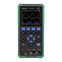
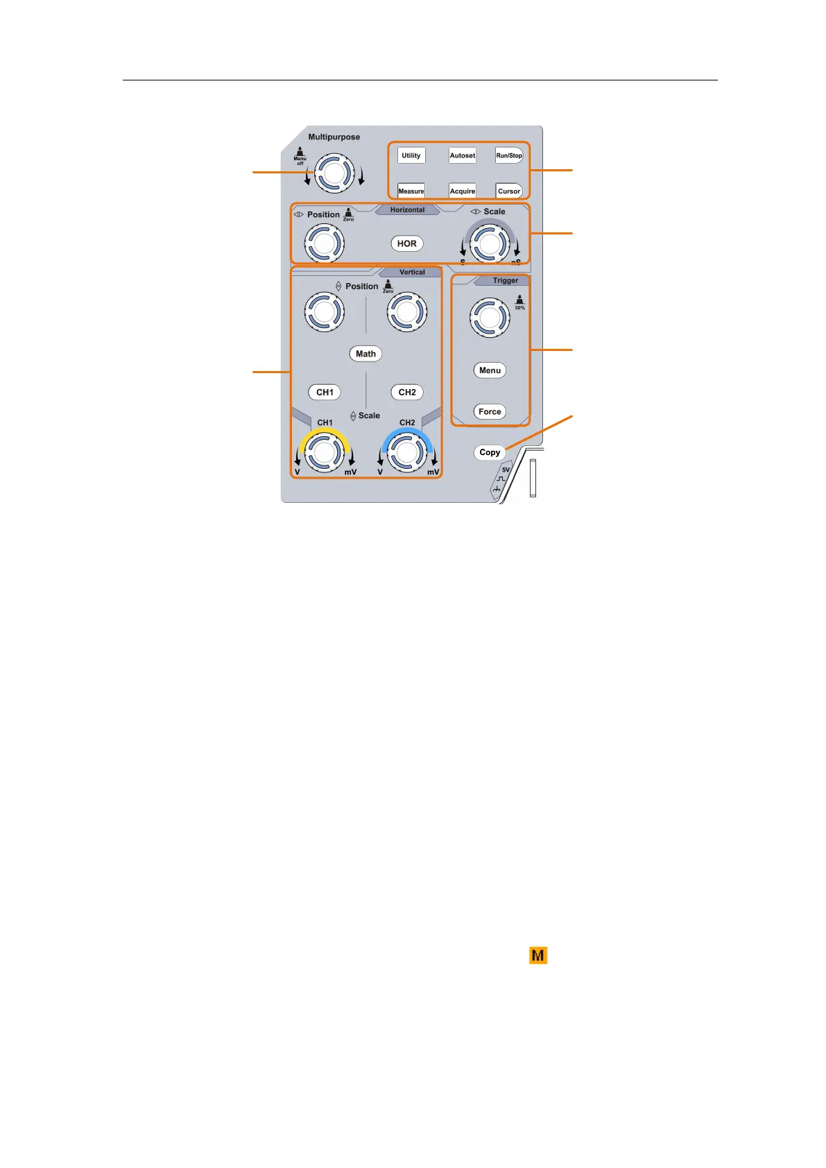
Figure 3-3 Control Area Overview
1. Function button area: Total 6 buttons.
2. Horizontal control area with 1 button and 2 rotary controls.
"HOR" button refer to horizontal system setting menu, "Horizontal Position" rotary
control control trigger position, " Horizontal Scale" control time base.
3. Trigger control area with 2 buttons and 1 rotary control.
The Trigger Level rotary control is to adjust trigger voltage. Other 2 buttons refer to
trigger system setting.
4. Copy button: This button is the shortcut for Save function in the Utility function
menu. Pressing this button is equal to the Save option in the Save menu. The
waveform, configure or the display screen could be saved according to the chosen type
in the Save menu.
5. Vertical control area with 3 buttons and 4 rotary controls.
"CH1" and "CH2 " correspond to setting menu in CH1 and CH2, "Math" button refer
to math menu, the math menu consists of six kinds of operations, including CH1-CH2,
CH2-CH1, CH1+CH2, CH1*CH2, CH1/CH2 and FFT. Two "Vertical Position"
rotary control control the vertical position of CH1/CH2, and two "Scale" rotary
control control voltage scale of CH1, CH2.
6. M rotary control(Multipurpose rotary control): when a symbol appears in the
menu, it indicates you can turn the M rotary control to select the menu or set the value.
You can push it to close the menu on the left and right.