MT CELL SETUP MANUAL MT556XNB, MT556UNB AND MT557D | 26
5 GET THE CELL INTO POSITION
Revision 3.0 www.multitaction.com
15.9.2020
P/N: MT2201012
5.4.1 Display wall installations
When planning and implementing display wall installations, remember the technical requirements
for heat management of the Cells, see section 4.3.
Ensure that Cells located in one ventilation space have a sufficient intake of cold air. (The typical
use for Multitaction Cell model is 150 m
3
per hour per Cell.)
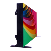
The following example of a 3x3 display wall of MT556XNB Cells provides general guidelines for the
design procedure. Each column of three Cells has its own cool air intake and hot air outlet with Air
Flow Cannels to separating the intake and outlet.
Front view: 3x3 display wall of MT556XNB Cells
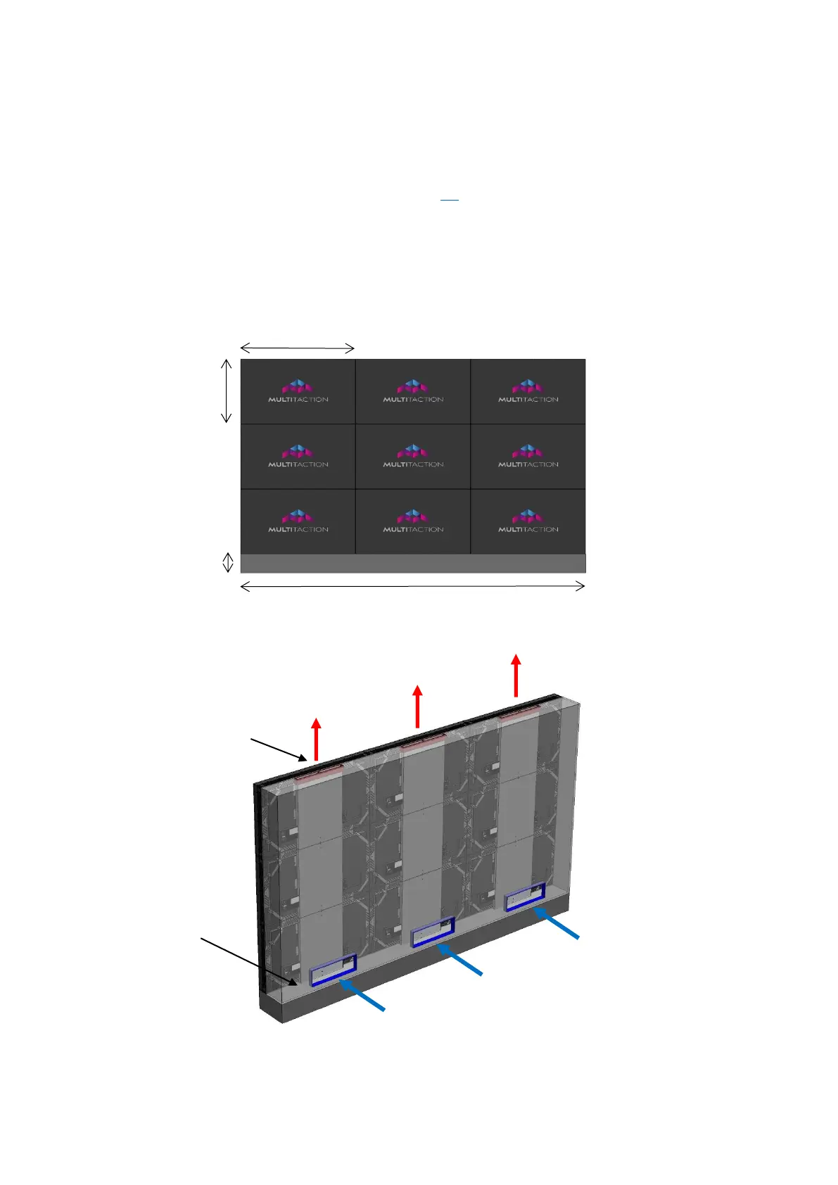
Isometric view: 3x3 display wall of Multitaction Cells
Physical Air Flaw Channels direct warm air out
Air Flow Channels
direct warm air out
Block warm air out
from bottom