Configuration/settings
User manual 55530_hdb_en_16 64 / 156
IO-Link master The IO-Link master has 2 or 4 IO-Link ports that can be allocated specific
IO-Link devices or can be set in SIO mode.
Read and write access to the IO-Link devices/ports.
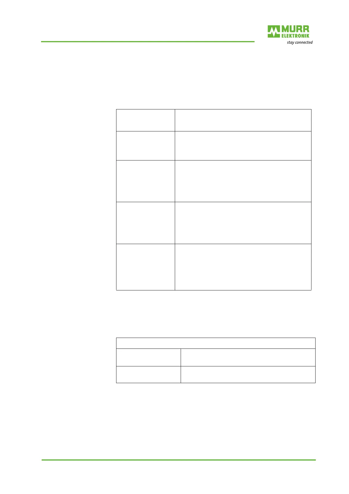
Tab. 8-5: Submodules for IO-Link master
Tab. 8-6: Example with Art.-No. 55518_submodule for IO-Link master
Submodules
Deactivated The corresponding IO-Link port is disabled, i.e. the
channel is neither used as a digital input or output,
nor as an IO-Link port.
IOL_I/O_SI 0 bytes In, 0 bytes Out
IO link standard IO mode.
The channel is addressed as digital input.
The data are read via "Digital IO".
IOL_I_x Byte x bytes In
IO link device with x byte(s) input data.
The status can be identified via the corresponding
bit in "Qualifier DI".
Parameterization of diagnostics and IO link proper-
ties is possible.
IOL_O_y Byte y bytes Out
IO link device with y byte(s) output data.
The status can be identified via the corresponding
bit in "Qualifier DO".
Parameterization of diagnostics and IO link proper-
ties is possible.
IOL_I/O_x/y Byte x bytes In, y bytes Out
IO link device with x byte(s) input data and y byte(s)
output data.
The status can be identified via the corresponding
bit in "Qualifier DI" and "Qualifier DO".
Parameterization of diagnostics and IO link proper-
ties is possible.
Example
Art.-No. 55518 MVP12-M DI8 DO8 IO-Link K3
Process data length
3 bytes of input data
1 byte of output data
Submodule
Smallest usable IO-Link submodule = IOL_I/O_4/2
bytes

 Loading...


