Rev. 9-24-14 Part #15-10683
www.NabcoEntrances.com GT 710-8710 Swing Door System Low Energy Operator
Install the First Half of Swing Arm 5-17
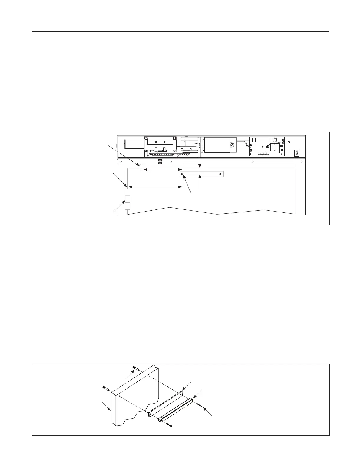
Go to the top edge of the Swing Door. Measure:
X 0 inch Reveal (Straight Arm):
• 11/16 inch from the top edge of the Swing Door down to the center of the Swing Door.
X Reveals greater than 0 inch (L-Shape Arm):
• 1-9/16 inch from the top edge of the Swing Door down to the center of the Swing Door.
X New dimension not shown (L-Shape Arm):
• Reveal + 8-7/8 inch = New dimension
Dim A
Center mark for
fi rst Sex Bolt Hole
DN 1088
Straight Arm
w/zero Reveal = 11/16”
L-Shape Arm
w/other Reveals = 1-9/16”
Center Pivot
Bu /Off set
(Inner Edge of Door Jamb)
Bu Hinge
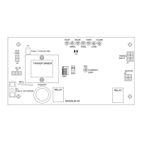
LED
TRANSFORMER
O
F
F
12
AUX
PWR
4
J2
3
J5
AC IN
F2
SW2
SW1
F1
RELAY
RELAY
J4
TDAS
SIGNAL
INPUT
TDPG
LCHK
CLOSE
Fuse 1: 0.5A 24 VAC
STOP
OPEN
BCHK
CURRENT
LIMIT
MOTOR
J1
R28
MAGNUM 4A
Fuse 2: 5A 120/240
Capacitor
MOV
ON
BACK
CHECK
SWITCH
DOOR
CLOSED
SWITCH
FOR
XXX HAND
UNITS
Figure 5-7 Measure to Mark the First Screw Hole
5.b.b: Secure the Track to the Swing Door
Ensure the Track is square and level.
Use the Track as a Template to mark the second Sex Bolt hole. Set aside.
Drill (2) 3/8 inch bolt holes all the way through the Swing door.
Go to the back of the Swing door. Insert each Sex Bolt into the drilled holes.
Go to the front of the Swing door. Butt the Track against the Swing door. Align the Sex Bolt holes.
a. If the wall/frame is not straight, vertical, plum etc., install (1) Spacer (21-0902) behind the
Track only if Reveal has a variance of zero to 1/4 inch and a Straight Arm is being installed.
b. A Spacer is used to prevent the Swing Arm from hitting the lip of the GT-710 Header only (the
GT-8710 Header does not have a lip).
c. If a Spacer can not be obtained, a couple of washers can be used.
Secure the Track to the Swing Door with (2) 1/4-20 x 2-1/4” Screws. Please see .
DN 1099
Spacer
Sex Bolt
Track
1/4-20 x 2-1/4”
Phillips Head Screw
Swing Door
A Spacer is only used with
a Straight Arm that is being
installed on GT-710 Units
to prevent the Swing Arm
hi ng the Lip of Header.
Figure 5-8 Secure the Track to the Swing Door