L NAPCO Security Systems
X GEM-P1664 Programming Instructions
Page 43
WI1423A 1/06
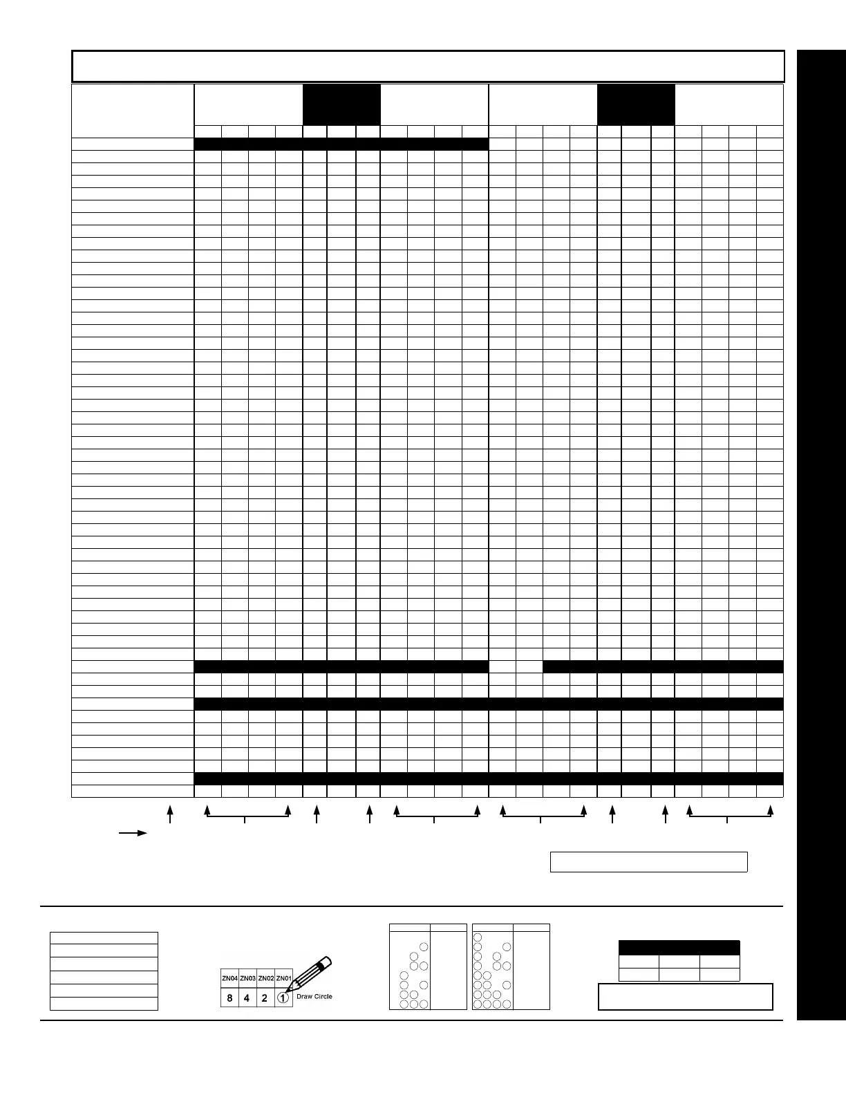
ZONE OPTIONS - ZONES 1 TO 16 (ADDRESS 0900-1016)
Direct Address Program Mode
ZONE OPTIONS ZONES 13-16
LEFT DATA VALUES
ADDRESS
ZONES 9-12
RIGHT DATA VALUES
ZONES 5-8
LEFT DATA VALUES
ADDRESS
ZONES 1-4
RIGHT DATA VALUES
ZN16 ZN15 ZN14 ZN13 L ADDR R ZN12 ZN11 ZN10 ZN9 ZN8 ZN7 ZN6 ZN5 L ADDR R ZN4 ZN3 ZN2 ZN1
50ms Loop Response (A) 8 4 2 1 0964 8 4 2 1 8 4 2 1 0900 8 4 2 1
Priority 8 4 2 1 0965 8 4 2 1 8 4 2 1 0901 8 4 2 1
Priority with Bypass 8 4 2 1 0966 8 4 2 1 8 4 2 1 0902 8 4 2 1
Auto-Bypass 8 4 2 1 0967 8 4 2 1 8 4 2 1 0903 8 4 2 1
Selective Bypass 8 4 2 1 0968 8 4 2 1 8 4 2 1 0904 8 4 2 1
Keyswitch Arming 8 4 2 1 0969 8 4 2 1 8 4 2 1 0905 8 4 2 1
Auto-Bypass Re-entry 8 4 2 1 0970 8 4 2 1 8 4 2 1 0906 8 4 2 1
Pre-Alarm Warning 8 4 2 1 0971 8 4 2 1 8 4 2 1 0907 8 4 2 1
Never Arm 8 4 2 1 0972 8 4 2 1 8 4 2 1 0908 8 4 2 1
24-Hour Zone 8 4 2 1 0973 8 4 2 1 8 4 2 1 0909 8 4 2 1
Alarm Output 8 4 2 1 0974 8 4 2 1 8 4 2 1 0910 8 4 2 1
Pulsed Alarm Output 8 4 2 1 0975 8 4 2 1 8 4 2 1 0911 8 4 2 1
PGM1 Output 8 4 2 1 0976 8 4 2 1 8 4 2 1 0912 8 4 2 1
PGM2 Output 8 4 2 1 0977 8 4 2 1 8 4 2 1 0913 8 4 2 1
Entry/Exit 1 8 4 2 1 0978 8 4 2 1 8 4 2 1 0914 8 4 2 1
Entry/Exit 2 8 4 2 1 0979 8 4 2 1 8 4 2 1 0915 8 4 2 1
Exit/Entry Follower 8 4 2 1 0980 8 4 2 1 8 4 2 1 0916 8 4 2 1
Auto Reset 8 4 2 1 0981 8 4 2 1 8 4 2 1 0917 8 4 2 1
Swinger Shutdown 8 4 2 1 0982 8 4 2 1 8 4 2 1 0918 8 4 2 1
Chime 8 4 2 1 0983 8 4 2 1 8 4 2 1 0919 8 4 2 1
Abort Delay 8 4 2 1 0984 8 4 2 1 8 4 2 1 0920 8 4 2 1
Power-up Delay 8 4 2 1 0985 8 4 2 1 8 4 2 1 0921 8 4 2 1
Day Zone Open 8 4 2 1 0986 8 4 2 1 8 4 2 1 0922 8 4 2 1
Day Zone Short 8 4 2 1 0987 8 4 2 1 8 4 2 1 0923 8 4 2 1
Alarm on Day Zone 8 4 2 1 0988 8 4 2 1 8 4 2 1 0924 8 4 2 1
Alarm Telco 1 8 4 2 1 0989 8 4 2 1 8 4 2 1 0925 8 4 2 1
Alarm Restore 1 8 4 2 1 0990 8 4 2 1 8 4 2 1 0926 8 4 2 1
Trouble Telco 1 8 4 2 1 0991 8 4 2 1 8 4 2 1 0927 8 4 2 1
Trouble Restore 1 8 4 2 1 0992 8 4 2 1 8 4 2 1 0928 8 4 2 1
Alarm Telco 3 8 4 2 1 0993 8 4 2 1 8 4 2 1 0929 8 4 2 1
Alarm Restore 3 8 4 2 1 0994 8 4 2 1 8 4 2 1 0930 8 4 2 1
Trouble Telco 3 8 4 2 1 0995 8 4 2 1 8 4 2 1 0931 8 4 2 1
Trouble Restore 3 8 4 2 1 0996 8 4 2 1 8 4 2 1 0932 8 4 2 1
No EOL Resistor 8 4 2 1 0997 8 4 2 1 8 4 2 1 0933 8 4 2 1
Trouble on Open 8 4 2 1 0998 8 4 2 1 8 4 2 1 0934 8 4 2 1
Trouble on Short 8 4 2 1 0999 8 4 2 1 8 4 2 1 0935 8 4 2 1
Zone Area 1 8 4 2 1 1000 8 4 2 1 8 4 2 1 0936 8 4 2 1
Zone Area 2 8 4 2 1 1001 8 4 2 1 8 4 2 1 0937 8 4 2 1
Interior (Stay) Bypass 8 4 2 1 1004 8 4 2 1 8 4 2 1 0940 8 4 2 1
Keypad Sounder on Alarm 8 4 2 1 1005 8 4 2 1 8 4 2 1 0941 8 4 2 1
2-Wire Smoke Detectors (B) 8 4 2 1 (•) 1006 (•) 8 4 2 1 8 4 2 1 0942 (•) 8 4 2 1
Fire (C) 8 4 2 1 1007 8 4 2 1 8 4 2 1 0943 8 4 2 1
Fire Alarm Verification (C) 8 4 2 1 1008 8 4 2 1 8 4 2 1 0944 8 4 2 1
RESERVED 8 4 2 1 (•) 1009 (•) 8 4 2 1 8 4 2 1 (•) 0945 (•) 8 4 2 1
Zone ANDing Group 1 8 4 2 1 1010 8 4 2 1 8 4 2 1 0946 8 4 2 1
Zone ANDing Group 2 8 4 2 1 1011 8 4 2 1 8 4 2 1 0947 8 4 2 1
Zone ANDing Group 3 8 4 2 1 1012 8 4 2 1 8 4 2 1 0948 8 4 2 1
Zone ANDing Group 4 8 4 2 1 1013 8 4 2 1 8 4 2 1 0949 8 4 2 1
Sensor Watch 8 4 2 1 1014 8 4 2 1 8 4 2 1 0950 8 4 2 1
RESERVED 8 4 2 1 1015 8 4 2 1 8 4 2 1 0951 8 4 2 1
Chime 2 8 4 2 1 1016 8 4 2 1 8 4 2 1 0952 8 4 2 1
When the Easy Program Menu is used, these features are enabled by default.
Enabled when "Enable SIA CP-01 Features?" is activated (Answer "Yes" in the EZ Programming Menu).
Disabled when "Enable SIA CP-01 Features?" is activated (Answer "Yes" in the EZ Programming Menu). Disable Auto-Reset on non-fire zones for SIA CP-01 installations.
Zone Area 3 8 4 2 1 1002 8 4 2 1 8 4 2 1 0938 8 4 2 1
Zone Area 4 8 4 2 1 1003 8 4 2 1 8 4 2 1 0939 8 4 2 1
1. Select the desired zone option.
s
ZONE OPTIONS
50ms Loop Response
Priority
Priority with Bypass
Auto-Bypass
Selective Bypass
3. Search table below for data entry. 4. Enter data in address locations (left and right
digits). Press [Enter] or [ON/OFF] to save.
L ADDR R
blank (•) 0490 1
ADDRESS LOCATION
NOTE: Dark shaded boxes = option not available.
See Direct Address Programming Example page 22.
4821
DIGIT VALUE DATA ENTRY
Blank (
.
)
4821
1
4821
2
8124
3
4821
4
5
4821
4821
6
4821
7
421
DIGIT VALUE DATA ENTRY
8
421
9
421
0
124
B
4 21
C
D
4 21
4 2 1
E
4 2 1
F
8
8
8
8
8
8
8
8
Step 1 Step 4 Step 4 Step 4 Step 4 Step 2 Step 2 Step 2 Step 2
See steps listed at
bottom of page
For notes (A), (B) and (C), see next page.
2. Enable desired options for each zone
by drawing a circle around its
corresponding binary data value. NOTE:
No circle = feature disabled.

 Loading...