8
W415-0794 / A / 06.08.10
3.0 VENTING
7.4
THIS APPLIANCE USES A 3” EXHAUST / 5” AIR INTAKE VENT PIPE SYSTEM.
Refer to the section applicable to your installation.
For safe and proper operation of the appliance follow the venting instruction exactly. Deviation from the
minimum vertical vent length can create diffi culty in burner start-up and/or carboning. Under extreme vent
confi gurations, allow several minutes (5-15) for the fl ame to stabilize after ignition. Vent lengths that pass
through unheated spaces (attics, garages, crawl spaces) should be insulated with the insulation wrapped in
a protective sleeve to minimize condensation. Provide a means for visually checking the vent connection to
the appliance after the appliance is installed. Use a fi restop, vent pipe shield or attic insulation shield when
penetrating interior walls, fl oor or ceiling.
NOTE: If for any reason the vent air intake system is disassembled; reinstall per the instructions
provided for the initial installation.
!
WARNING
RISK OF FIRE, MAINTAIN SPECIFIED AIR SPACE CLEARANCES TO VENT PIPE AND APPLIANCE.
IF VENTING IS INCLUDED WITH SPACERS THE VENT SYSTEM MUST BE SUPPORTED EVERY 3 FEET
FOR BOTH VERTICAL AND HORIZONTAL RUNS. USE SUPPORTS OR EQUIVALENT
NON-COMBUSTIBLE STRAPPING TO MAINTAIN THE REQUIRED CLEARANCE FROM
COMBUSTIBLES. USE WOLF STEEL LTD. SUPPORT RING ASSEMBLY W010-0370 OR EQUIVALENT
NON-COMBUSTIBLE STRAPPING TO MAINTAIN THE MINIMUM CLEARANCE TO COMBUSTIBLES
FOR BOTH VERTICAL AND HORIZONTAL RUNS. SPACERS ARE ATTACHED TO THE INNER PIPE AT
PREDETERMINED INTERVALS TO MAINTAIN AN EVEN AIR GAP TO THE OUTER PIPE. THIS GAP IS
REQUIRED FOR SAFE OPERATION. A SPACER IS REQUIRED AT THE START, MIDDLE AND END OF
EACH ELBOW TO ENSURE THIS GAP IS MAINTAINED. THESE SPACERS MUST NOT BE REMOVED.
3.1 VENTING LENGTHS AND COMPONENTS
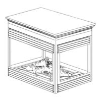
The vent connection to the appliance can be viewed by removing the baffl e from the top, inside of the fi rebox.
Use only Wolf Steel venting components. Minimum and maximum vent lengths, for both horizontal and
vertical installations, and air terminal locations for either system are set out in this manual and must be
adhered to. Use only Wolf Steel Ltd. fl exible vent components with the Wolf Steel Ltd. GD179
termination kit. This appliance uses a 3” diameter exhaust and a 5” diameter intake coaxial vent system.
All outer pipe joints of these venting systems must be sealed using Red RTV and/or Mill Pac high temperature
sealant (not supplied) hereafter referred to as high temperature sealant W573-0002 (Red RTV) and the high
temperature sealant W573-0007 (Mill Pac).
For vent systems that provide seals on the inner exhaust fl ue, only the outer air intake joints must be sealed
using a red high temperature silicone (RTV). This same sealant may be used on both the inner exhaust and
outer intake vent pipe joints of all other approved vent systems except for the exhaust vent pipe connection to
the appliance fl ue collar which must be sealed using the black high temperature sealant Mill Pac.
With fl exible venting, in conjunction with the GD178 wall terminal kit, use either the 5 foot vent kit GDT5 or
the 10 foot vent kit GDT10. These kits allow for extended horizontal venting of the appliance.
When using approved Wolf Steel venting components, use only the following termination kits: WALL
TERMINAL KIT GD178, or 1/12 TO 7/12 PITCH ROOF TERMINAL KIT GDT110, 8/12 TO 12/12 ROOF
TERMINAL KIT GDT111, FLAT ROOF TERMINAL KIT GDT112.
For optimum fl ame appearance and appliance performance, keep the vent length and number of
elbows to a minimum.
The air terminal must remain unobstructed at all times. Examine the air terminal at least once a year
to verify that it is unobstructed and undamaged.
Rigid and fl exible venting systems must not be combined. Different venting manufacturer
components must not be combined.
 Loading...