W415-2845 / B / 11.10.20
22
IOM
IOM
9.1 VENT TERMINATION
The periscope vent (fi gure 9), must be used in extreme cold climates defi ned as; -22°F (-30°C)
sustained for 48 hours or more.
Take the building orientation and the presence of other buildings or other nearby structures into consideration
when planning the venting system location. Certain external structures could create air turbulence around the
vent termination leading to downdrafts and similar venting problems. In windy and hill locations, roof venting
may improve operations. Maximum venting length is based on 30 mph (48 km) winds, areas where higher
gusts are dominant it is suggested to shorten the horizontal vent length.
When installing the furnace with direct venting, the vent and combustion air intake shall be installed so that
both are located in the same wind pressure zone.
H3.13
DO NOT CONNECT FURNACE TO A CHIMNEY OR FLUE SERVING OTHER APPLIANCES OR A
SOLID FUEL BURNING APPLIANCE.
WARNING
!
!
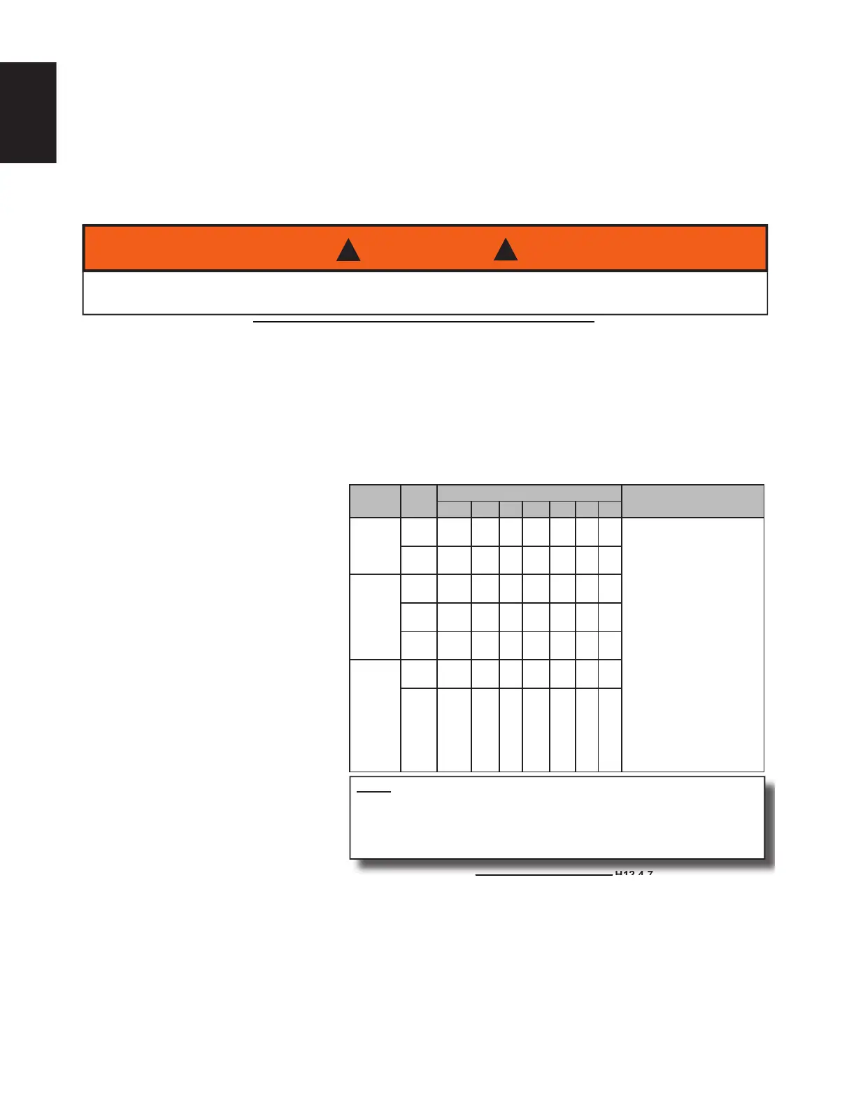
TABLE 4 - DIRECT AND NON-DIRECT VENT LENGTHS
Maximum Allowable Length Of Exhaust Or Intake. Minimum Vent Length 15 ft. (4.6 m) or equivalent.
INPUT
K/Btu/hr
PIPE
SIZE
NUMBER OF 90° ELBOWS
NOTES
0123456
40**
1½ 60* 55 50 45 40 35 30
1. Count concentric vent
fi tting as straight pipe.
2. Use medium or long
sweep elbows where
possible.
3. One 90° elbow is
equivalent to two 45°
elbows.
4. For direct vent, the
listed lengths are
allowed for each vent
(intake and exhaust).
5. For non-direct vent,
the listed lengths are
allowed for exhaust.
The intake should have
a 1½” or 2” snorkel
intake fi tting. (Figure 7)
2,2½ 75* 70 65 60 55 50 45
60
1½ 60* 55 50 45 40 35 30
2,2½ 75* 70 65 60 55 50 45
3 100* 95 90 85 80 75 70
80
2,2½ 50* 45 40 35 30 25 20
3 100* 95 90 85 80 75 70
H12.4.7
NOTE When 1½", 2½” or 3" pipe is used, exit the cabinet with 2" pipe.
Reduce or increase immediately after exiting the cabinet on both intake and
exhaust.
* Maximum allowable vent (intake and exhaust) length.
** 40 K units must be vented with 1½" venting if total run length is to be less
than 25 ft. (7.6m).
orizontal vents should pass through the exterior wall. Figure 8 shows a standard horizontal vent detail.
erminate the vent 8” (203mm) or more from the wall.
xterior vent pipe greater than 24” (610mm) should be insulated with 1/2” (13mm) insulation to prevent
oisture from freezing within the pipe and accumulating.
ize the exhaust pipe as specifi ed in
Table 4 - Direct and Non-Direct Vent
engths. This table lists the maximum
llowable length of pipe with respect to
he number of 90° elbows used. For the
urposes of this calculation, one 90°
lbow is equivalent to two 45° elbows.
Avoid locating the terminal in locations
here dripping condensate may cause
problems such as sidewalks, patios,
above planters, near windows where
exhaust gases may cause fogging, etc.
Avoid locating the termination too close
to shrubs and other vegetation. The
condensate may stunt or kill them.
EQUIVALENTS
Short Radius Elbow = 7 ft (2.13m)
Standard Radius Elbow = 5 ft (1.52m)
Long Radius Elbow = 3 ft (0.91m)
45 Degree Elbow = 2.5 ft (0.76m)
Tee
Vent lengths that require more than
6-90° elbows, add listed equivalents
for every elbow up to the maximum
allowable vent length.
 Loading...