2.0 SAFETY ISSUES
H25.0.1
This furnace has been designed to deliver many years of effi cient, dependable service. With regular
maintenance, some of which requires the attention of a qualifi ed installer, service agency or gas supplier,
some of which you may do yourself, the furnace will operate satisfactorily over many heating seasons.
Please read this manual to familiarize yourself with safety procedures, operation, and routine maintenance
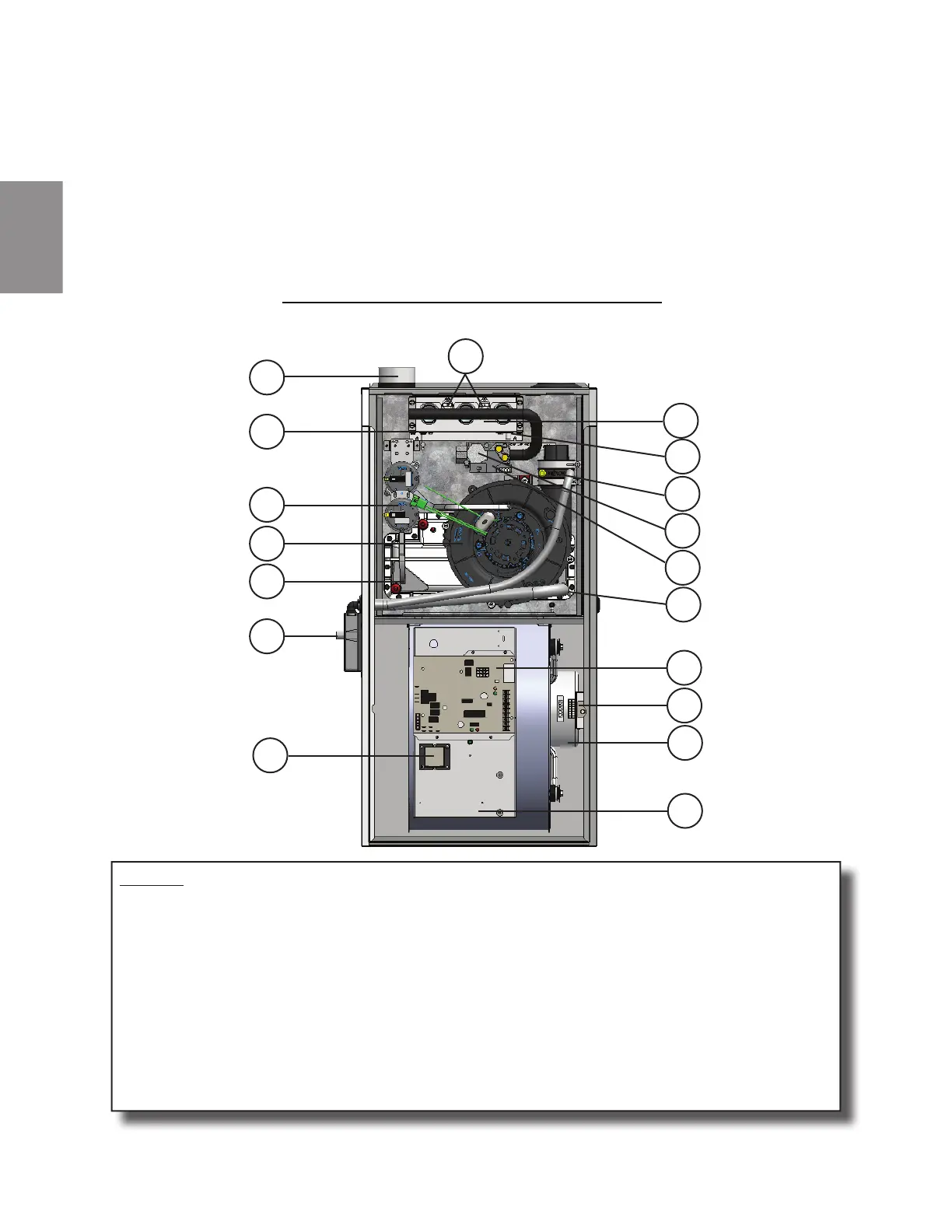
procedures. Figure 1 is provided to help identify the components of your furnace.
Do not use this furnace if any part has been under water. A fl ood-damaged furnace is extremely dangerous.
Attempts to use the furnace can result in fi re or explosion. A qualifi ed service agency should be contacted to
inspect the furnace and to replace all gas controls, control system parts, electrical parts that have been wet or
the furnace, if deemed necessary.
FIGURE 1 - FURNACE COMPONENTS
LEGEND
1. Combustion Air Intake Fitting 11. Burner Assembly
2. Flame Roll-Out Switch (2) 12. Hot Surface Igniter (HSI) - located underneath
3. Flame Sensor - located underneath 13. Two Speed Exhauster
4. Two Stage Gas Valve 14. Pressure Switch Assembly
5. Air High Temperature Limit (behind gas valve) 15. Front Manifold Cover Pressure Tap (3)
6. Vent and Drain Assembly 16. Door Switch and Junction Box
7. Drain for Recovery Coil (3) 17. Blower Motor
8. Condensate Trap Assembly 18. Circulating Air Blower
9. Two Stage Integrated Furnace Control (IFC)
10. Transformer for 24 VAC / 40 VA
1
14
13
3
15
10
8
2
11
12
5
6
4
7
9
16
17
18
W415-2845 / B / 11.10.20
66
UM
 Loading...