Getting Started with NI 7340/7350 Controllers and AKD Drives | © National Instruments | 9
1. Connect the SHC68-C68-S 68-pin shielded cable between the Motion I/O connector on the
NI 7340/7350 motion controller and the Motion I/O connector on the UMI-7772/74.
2. Connect the UMI-7772/74 to AKD Drive Cable to the Control and Feedback connectors on
the UMI-7772/74.
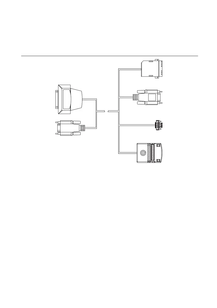
Figure 3 shows the UMI-7772/74 to AKD Drive Cable connectors.
Figure 3. UMI-7772/74 to AKD Drive Cable Connectors
The UMI-7772/74 to AKD Drive Cable contains the following connections:
• UMI-7772/74 Feedback Connector—25-pin DSUB connector containing encoder,
limit, and home sensor signals.
• UMI-7772/74 Control Connector—15-pin DSUB connector containing drive
command and drive enable signals.
• X8 10-Pin Connector—10-pin connector containing the servo command, enable, and
fault signals.
• X9 DSUB Connector—9-pin DSUB connector containing emulated encoder output
signals from the AKD servo drive.
• X1 3-pin Connector—+24 V power supply connection for the AKD servo drive.
• Screw Terminal Connector—20-pin screw terminal connector for external I/O
connections. Table 1 shows the UMI-7772/74 to AKD Drive Cable screw terminal
pinout.
X9
Screw Terminal
Connector
X1 3-Pin
Connector
X8 10-Pin
Connector
X9 DSUB
Connector
UMI-7772/74
Feedback
Connector
UMI-7772/74
Control
Connector
 Loading...