10 | ni.com | Getting Started with NI 7340/7350 Controllers and AKD Drives
3. Configure the UMI-7772/74 DIP switches. You must set the UMI-7772/74 switches to the
following settings to match the polarity configuration for the AKD servo drive:
• Fault—Active Low
• Enable—Active Low
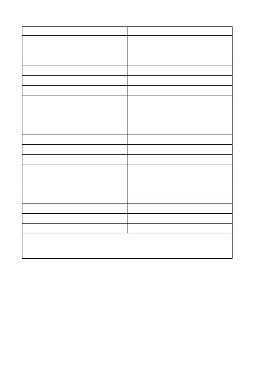
Table 1. UMI-7772/74 to AKD Drive Cable Screw-Terminal Pinout
Pin Signal Name
1 Forward Limit
2 Home
3 Reverse Limit
4 COM
†
5 +24 V OUT
6 COM
†
7 NC
‡
8 NC
‡
9 NC
‡
10 Digital Ground
†
11 +5 V (Output)
12 Reserved
13 Reserved
14 Digital Ground
†
15 Reserved
16 Reserved
17 Reserved
18 Reserved
19 Reserved
20 Reserved
†
The COM and Digital Ground signals are tied together if you connect the C and Ciso terminals on the
UMI-7772/74 as shown in Figure 5.
‡
NC = Not Connected
 Loading...