Getting Started with NI 7340/7350 Controllers and AKD Drives | © National Instruments | 11
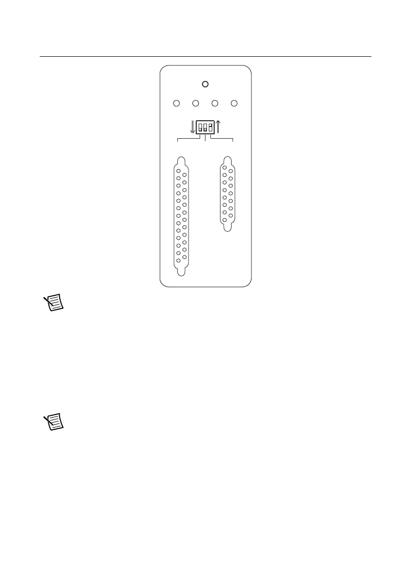
The UMI-7772/74 DIP switch configuration is shown in Figure 4.
Figure 4. UMI-7772/74 Fault and Enable DIP Switch Settings
Note Configuring the limit and home status LEDs on the UMI-7772/74 does not
configure the limit and home inputs themselves as active-high or active-low. You
must configure the limit and home inputs separately on the National Instruments
motion controller using MAX or the NI-Motion driver software. This DIP switch
does not need to be configured when the UMI-7772/74 is used with the AKD servo
drive.
4. Connect the positive lead of the +24 V external power supply to the V terminal and the
negative lead to the C terminal, then connect the V terminal to the V
iso
terminal and the
C terminal to the C
iso
terminal.
Note You may use the same +24 V power supply to power both the UMI-7772/74
and the AKD drive. However, ensure that the power supply is capable of delivering
enough current for the application. If you require more power, connect a separate
+24 V power supply to the AKD drive X1 connector as described in
Step 4: Connect
the Logic Power Supply to the AKD Servo Drive
.
18
19
20
21
22
23
24
25
17
16
15
14
1
6
7
8
9
10
11
12
13
5
4
3
2
AXIS 1
DISABLED
FAULT FWD HOME REV
ACTIVE
LOW
ACTIVE
HIGH
LIMIT LED
FAULT ENABLE
CONTROL
FEEDBACK
1
2
3
4
5
6
7
8
9
10
11
12
13
14
15
 Loading...