12 | ni.com | Getting Started with NI 7340/7350 Controllers and AKD Drives
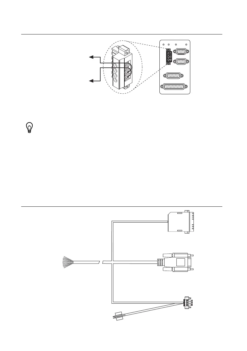
Figure 5 shows the power terminal block.
Figure 5. UMI-7772/74 Power Connection
Connecting a UMI-7764
Complete the following steps to connect and configure your UMI-7764.
Tip For more information about connecting external power, encoders, and other
motion I/O signals, refer to the Universal Motion Interface (UMI)-7764 User Guide
and Specifications.
1. Connect the SH68-C68-S 68-pin shielded cable between the Motion I/O connector on the
NI 7340/7350 motion controller and the Motion I/O connector on the UMI-7764.
2. Connect the UMI-7764 to AKD Drive cable to the UMI-7764 by connecting the leads from
the cable to the correct screw terminal. The leads are labeled with the same signal names as
the NI UMI-7764.
Figure 6 shows the UMI-7764 to AKD Drive Cable connectors.
Figure 6. UMI-7764 to AKD Drive Cable
C
V
Viso
Ciso
+24 V External
Supply(+) Terminal
V
(24VDC±10%)
(5-30VDC)
Viso INHIBIT ALL
POWER
POWER
TRIGGER / BREAKPOINT
DIGITAL I/O
ANALOG INPUT
GLOBAL STOP
INTERLOCK
+24 V External
Supply(–) Terminal
V
Viso
Ciso
C
X1 3-Pin
Connector
X8 10-Pin
Connector
X9 DSUB
Connector
UMI-7764 Screw
Terminal Leads
X9
+24V
GND
+24V Power
Supply Leads
 Loading...