18 | ni.com | Getting Started with NI 7340/7350 Controllers and AKD Drives
The +24 V logic power supply also powers the safe torque output (STO) input on the X1
connector. The STO input must be powered by +24V for proper drive operation. If you need to
use the STO functionality complete the following additional steps:
1. Disconnect the STO wire from UMI-7764 to AKD cable from the from the X1 connector
and insulate it.
Note The STO and +24V wires are internally connected in the UMI-7774 to AKD
cable. You must insulate the STO wire if you disconnect it from the X1 connector.
2. Connect the STO terminal and GND terminal to the output of a safety relay or security
control. The safety relay must comply with the requirements of the SIL 2 according to
IEC 61800-5-2, PL d according to ISO 13849-1, or Category 3 according to EN-954. Refer
to the AKD Installation Manual for more information.
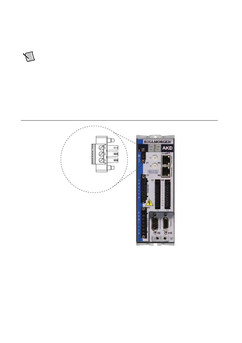
Figure 11 shows the X1 connector pin assignment and wire colors.
Figure 11. UMI-7764 to AKD Cable X1 Connector
+24 V (Red)
GND (Black)
STO (Brown)
X1 3-Pin
Connector
 Loading...