Getting Started with NI 7340/7350 Controllers and AKD Drives | © National Instruments | 17
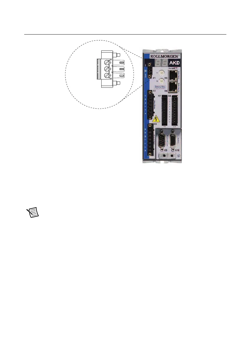
Figure 10 shows the X1 connector pin assignment and wire colors.
Figure 10. UMI-7772/74 to AKD Cable X1 Connector
Using a UMI-7764
The +24 V power supply provides the logic power to the AKD servo drive.
Complete the following steps to connect the +24 V power supply to the UMI-7764 to AKD
cable. Figure 6 shows the UMI-7764 to AKD Drive Cable +24V power supply leads.
Note Do not plug in or turn on the +24 V power supply until after you complete
Step 7: Connect the Drive Communication in the NI UMI and AKD Servo Drive
Configuration and Installation
section.
1. Connect the +24 V power supply (+) terminal to the wire labeled +24V on the UMI-7764
to AKD cable.
2. Connect the +24 V power supply return (–) terminal to the wire labeled GND on the
UMI-7764 to AKD cable.
X1 3-Pin
Connector
+24 V
GND (Black)
STO
 Loading...