Chapter 8 Counters
© National Instruments Corporation 8-7 NI USB-621x User Manual
Buffered Period Measurement
Buffered period measurement is similar to single period measurement, but
buffered period measurement measures multiple periods.
The counter counts the number of rising (or falling) edges on the Source
input between each pair of active edges on the Gate input. At the end of
each period on the Gate signal, the counter stores the count in a hardware
save register. A USB Signal Stream transfers the stored values to host
memory.
The counter begins on the first active edge of the Gate after it is armed. The
arm usually occurs in the middle of a period of the Gate input. The counter
does not store a measurement for this incomplete period.
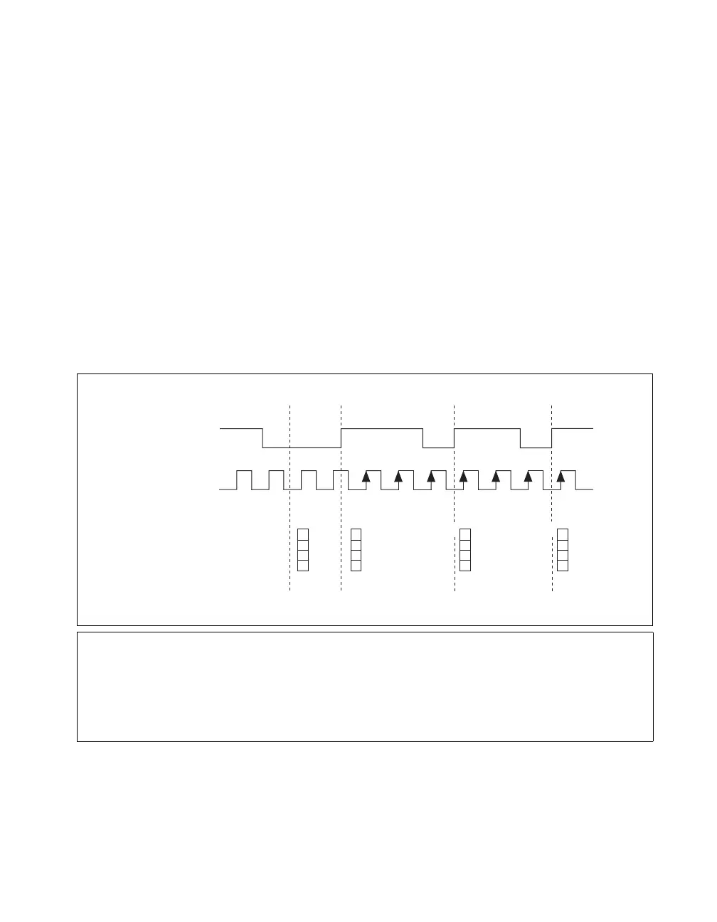
Figure 8-8 shows an example of a buffered period measurement. In this
example, a period is defined by two consecutive rising edges.
Figure 8-8. Buffered Period Measurement
t
0
At t
0
, the counter is armed. No measurements are taken until the counter is armed.
t
1
The rising edge of Gate indicates the beginning of the first period to measure. The counter begins counting
rising edges of Source.
t
2
The rising edge of Gate indicates the end of the first period. The USB-621x device stores the counter value
in the buffer.
t
3
The rising edge of Gate indicates the end of the second period. The USB-621x device stores the counter value
in the buffer.
SOURCE
GATE
Counter Value
Buffer
1 3
3
311
2
2
3
3
3
Counter Armed
Time N
3
t
0
t
1
t
2
t
3

 Loading...


