Chapter 4 Analog Input
© National Instruments Corporation 4-37 NI USB-621x User Manual
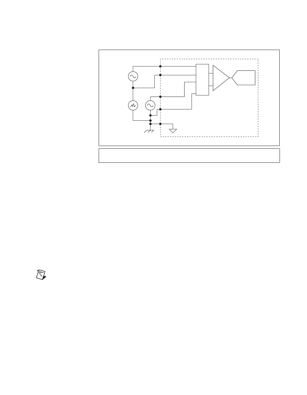
Figure 4-24 shows a differential connection configuration.
Figure 4-24. Connecting to the USB-6215/6216/6218 in Differential Mode
The differential connection configuration allows the common-mode noise
voltage, V
cm
, to be rejected during the measu rement of V
1
.
You must connect the negative lead of your sensors and AI GND to a local
ground signal on your system.
Taking Referenced Single-Ended Measurements
Using the referenced single-ended measurement configuration allows the
USB-6215/6216/6218 to take measurements on all AI channels when all
channels share a common ground. Figure 4-25 shows an referenced
single-ended connection configuration.
Note If you leave the AI GND pin unconnected, the signals float outside the working input
range of the USB-6215/6216/6218. This can result in unreliable measurements because
you cannot ensure that the input signal is within 10 V of AI GND.
* This signal name indicates the differential pair. Refer to Table 3-1, I/O Connector
Signals, for a list of differential signal pairs.
AI 0+
AI 0– (AI 8)*
Mux
AI 1+
AI 1– (AI 9)*
AI GND
V
1
V
2
V
cm
ADC
PGIA
USB-6215/6216/6218

 Loading...


