Chapter 4 Analog Input
© National Instruments Corporation 4-19 NI USB-621x User Manual
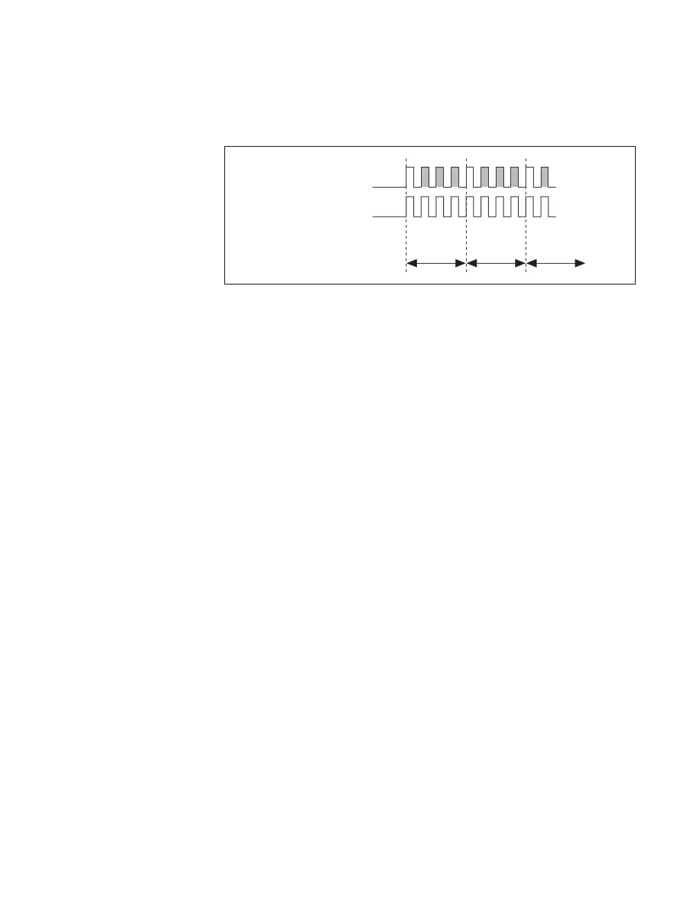
A single external signal can drive both AI Sample Clock and AI Convert
Clock at the same time. In this mode, each tick of the external clock causes
a conversion on the ADC. Figure 4-14 shows this timing relationship.
Figure 4-14. Single External Signal Driving AI Sample Clock and
AI Convert Clock Simultaneously
AI Convert Clock Timebase Signal
The AI Convert Clock Timebase (ai/ConvertClockTimebase) signal is
divided down to provide one of the possible sources for AI Convert Clock.
Use one of the following signals as the source of AI Convert Clock
Timebase:
• AI Sample Clock Timebase
• 20 MHz Timebase
AI Convert Clock Timebase is not available as an output on the
I/O connector.
AI Hold Complete Event Signal
The AI Hold Complete Event (ai/HoldCompleteEvent) signal generates a
pulse after each A/D conversion begins. You can route AI Hold Complete
Event out to any output PFI terminal.
The polarity of AI Hold Complete Event is software-selectable, but is
typically configured so that a low-to-high leading edge can clock external
AI multiplexers indicating when the input signal has been sampled and can
be removed.
AI Sample Clock
AI Convert Clock
Sample #1 Sample #2 Sample #3
1 2 3 0
1 2 3 0 1 … 0
Channel Measured

 Loading...


