Chapter 8 Counters
© National Instruments Corporation 8-35 NI USB-621x User Manual
Cascading Counters
You can internally route the Counter n Internal Output and Counter n TC
signals of each counter to Gate inputs of the other counter. By cascading
two counters together, you can effectively create a 64-bit counter. By
cascading counters, you also can enable other applications. For example,
to improve the accuracy of frequency measurements, use reciprocal
frequency measurement, as described in the Method 3 bullet of the
Frequency Measurement section.
Counter Filters
You can enable a programmable debouncing filter on each PFI signal.
When the filters are enabled, your device samples the input on each rising
edge of a filter clock. USB-621x devices use an onboard oscillator to
generate the filter clock with a 40 MHz frequency.
Note NI-DAQmx only supports filters on counter inputs.
The following is an example of low-to-high transitions of the inpu t signal.
High-to-low transitions work similarly.
Assume that an input terminal has been low for a long time. The input
terminal then changes from low-to-high, but glitches several times. When
the filter clock has sampled the signal high on N consecutive edges, the
low-to-high transition is propagated to the rest of the circuit. The value of
N depends on the filter setting; refer to Table 8-5.
The filter setting for each input can be configured independently. On power
up, the filters are disabled. Figure 8-31 shows an example of a low-to-high
transition on an input that has its filter set to 125 ns (N = 5).
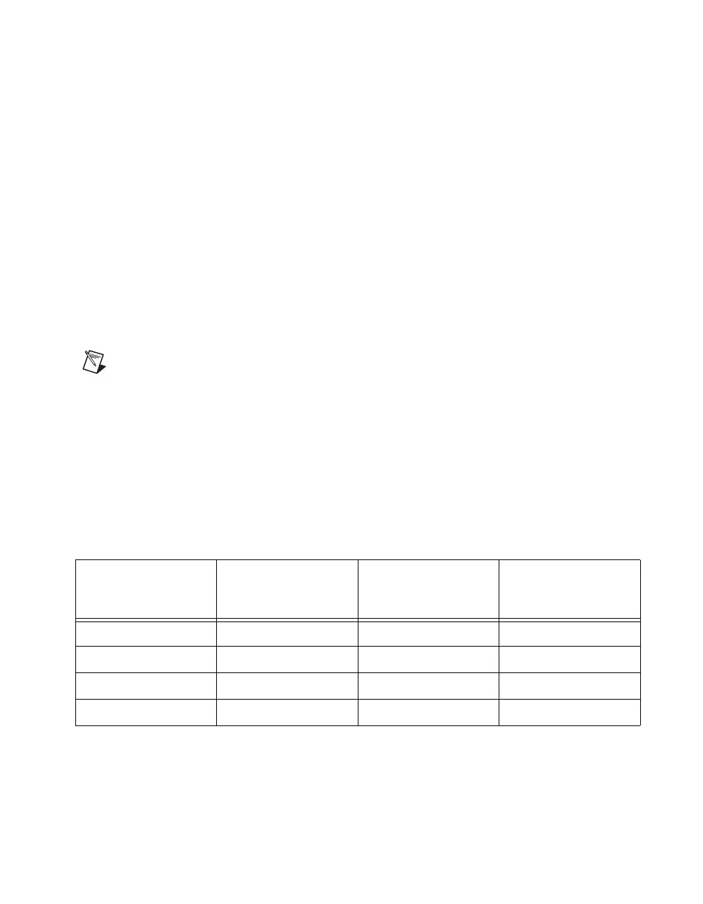
Table 8-5. Filters
Filter Setting
N (Filter Clocks
Needed to
Pass Signal)
Pulse Width
Guaranteed to
Pass Filter
Pulse Width
Guaranteed to
Not Pass Filter
125 ns 5 125 ns 100 ns
6.425 μs 257 6.425 μs 6.400 μs
2.56 ms ~101,800 2.56 ms 2.54 ms
Disabled — — —
 Loading...


