© National Instruments Corporation 4-1 NI USB-621x User Manual
4
Analog Input
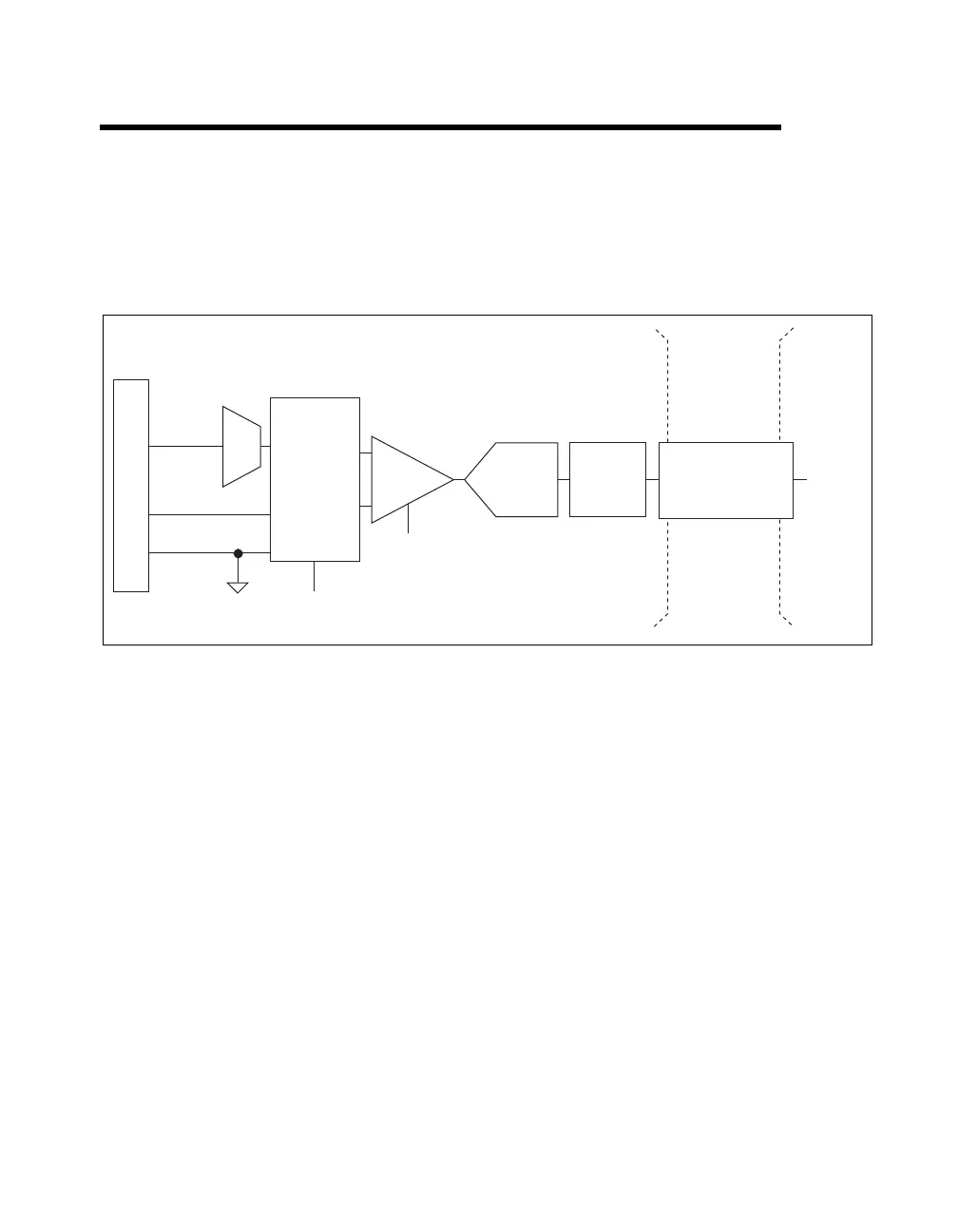
Figure 4-1 shows the analog input circuitry of USB-621x devices.
Figure 4-1. USB-621x Analog Input Circuitry
The main blocks featured in the USB-621x analog input circuitry are as
follows:
• I/O Connector—You can connect analog input signals to the
USB-621x device through the I/O connector. The proper way
to connect analog input signals depends on the analog input
ground-reference settings, described in the Analog Input
Ground-Reference Settings section. Also refer to Appendix A,
Device-Specific Information, for device I/O connector pinouts.
• Mux—Each USB-621x device has one analog-to-digital converter
(ADC). The multiplexers (mux) route one AI channel at a time to the
ADC through the NI-PGIA.
• AI Ground-Reference Settings—The analog input ground-reference
settings circuitry selects between differential (DIFF), referenced
single-ended (RSE), and non-referenced single-ended (NRSE) input
modes. Each AI channel can use a different mode.
DIFF, RSE,
or NRSE
I/O Connector
AI <0..n>
Mux
AI SENSE
AI GND
NI-PGIA
AI Ground-Reference
Settings
Input Range
Selection
ADC
AI FIFO
AI Data
Digital
Isolators
Isolation
Barrier
(USB-6215/
6216/6218
devices only)

 Loading...


