Chapter 3 Connector and LED Information
NI USB-621x User Manual 3-3 ni.com
+5 V Power
The +5 V terminals on the I/O connector can be use as either an output or
an input. Both terminals are internally connected on the USB-621x.
+5 V Power as an Output
Because the USB-621x devices are bus powered, there is a 50 mA limit on
the total current that can be drawn from the +5 V terminals and the digital
outputs. The USB-621x monitors the total current and drops the voltage
on all of the digital outputs and the +5 V terminals if the 50 mA limit is
exceeded.
+5 V Power as an Input
If you have high current loads for the digital outputs to drive, you can
exceed the 50 mA internal limit by connecting an external +5 V power
source to the +5 V terminals. These terminals are protected against
undervoltage and overvoltage, and they have a fuse to protect them from
short circuit conditions
1
. If your USB-621x device has more than one +5 V
terminal, you can connect the external power supply to one terminal and
use the other as a power source.
USER — — (USB-621x BNC Devices) User-Defined Channel—The USER
BNC connector allows you to use a BNC connector for a digital
or timing I/O signal of you r choice. The USER BNC connector
is internally routed to the USER screw terminal. Refer to the
appropriate USER section for your USB-621x BNC device in
Appendix A, Device-Specific Information, for more
information about the USER signal.
NC — — No connect—Do not connect signals to these terminals.
*
USB-6212/6216 BNC/Mass Termination devices have eight digital I/O lines, P0.<0..7>.
1
USB-621x Screw Terminal/BNC devices have a 350 mA self-resetting fuse. USB-621x Mass Termination devices have a
750 mA user-replaceable socketed fuse. Refer to the USB Device Fuse Replacement section for information about replacing
socketed fuses.
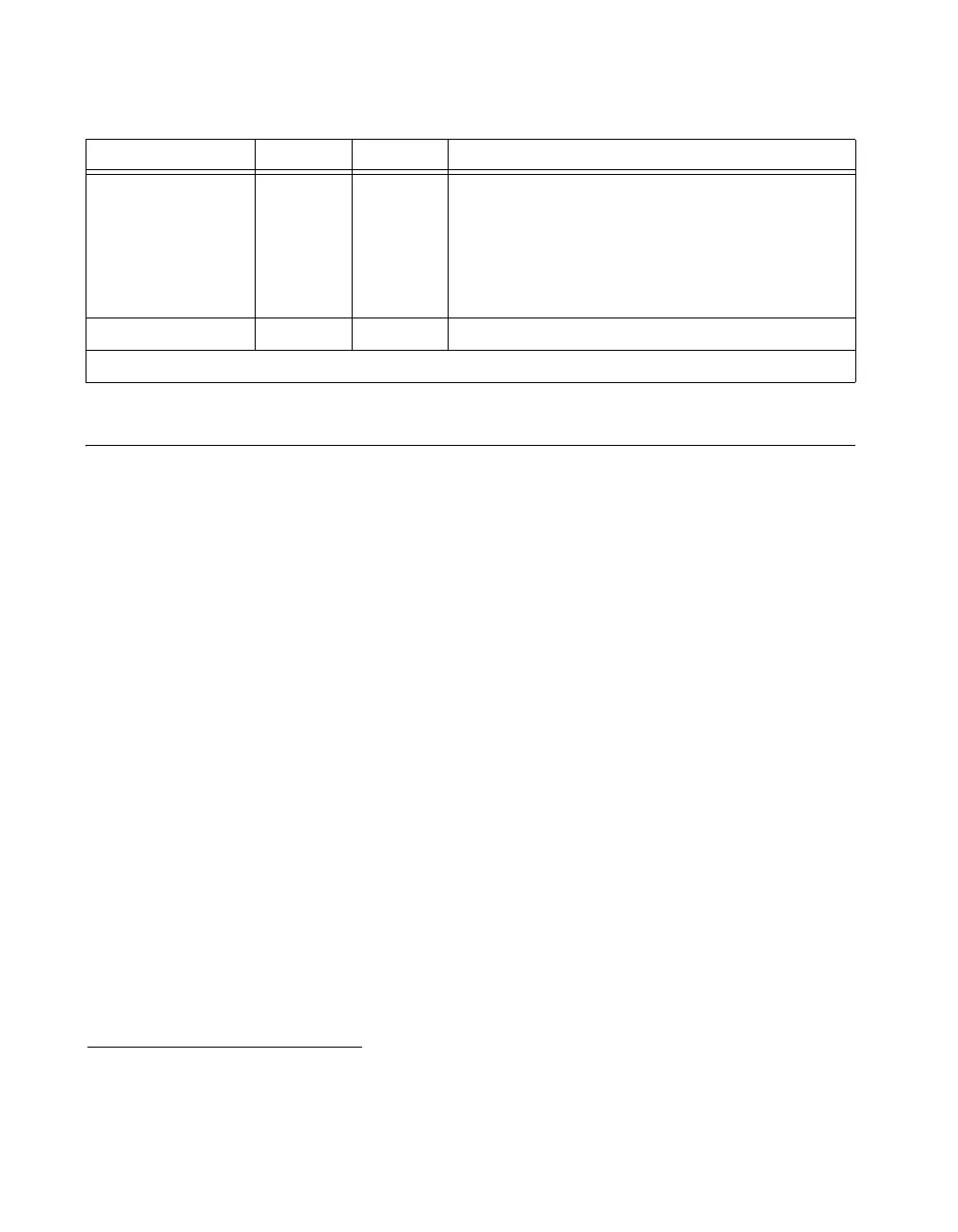
Table 3-1. I/O Connector Signals (Continued)
Signal Name Reference Direction Description

 Loading...


