© National Instruments Corporation 3-1 NI USB-621x User Manual
3
Connector and LED Information
The I/O Connector Signal Descriptions and +5 V Power sections contain
information about NI USB-621x connectors. The PWR/ACT LED Indicator
section contains information about the NI USB-621x PWR/ACT LED.
Refer to Appendix A, Device-Specific Information, for device I/O
connector pinouts. Refer to the Applying Signal Labels to the USB-621x
section of Chapter 1, Getting Started, for information about applying signal
labels.
I/O Connector Signal Descriptions
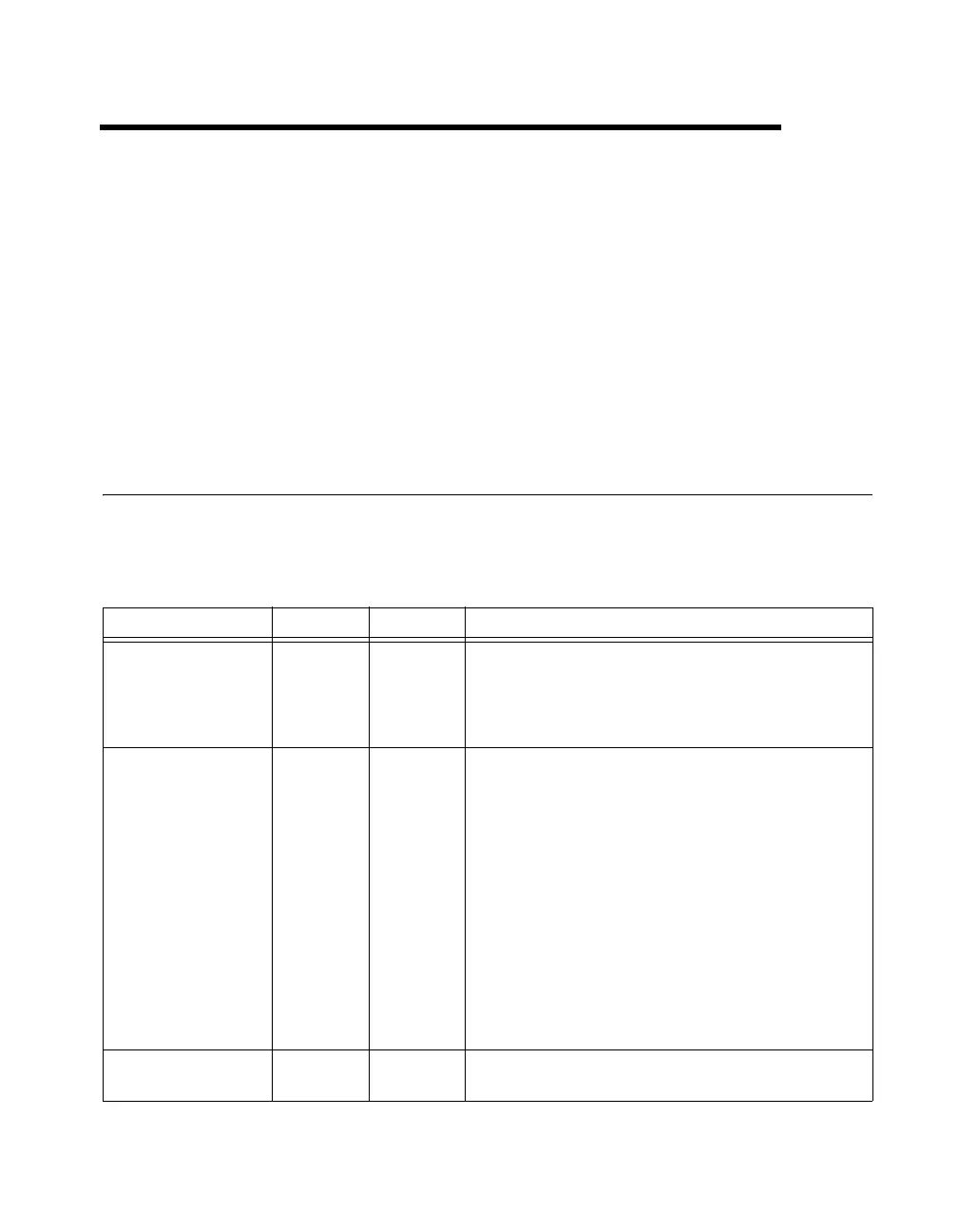
Table 3-1 describes the signals found on the I/O connectors. Not all signals
are available on all devices.
Table 3-1. I/O Connector Signals
Signal Name Reference Direction Description
AI GND — — Analog Input Ground—These terminals are the reference
point for single-ended AI measurements in RSE mode and the
bias current return point for differential measurements. All three
ground references—AI GND, AO GND, and D GND—are
connected on the device.
AI <0..31> Varies Input Analog Input Channels 0 to 31—For single-ended
measurements, each signal is an analog input voltage channel.
In RSE mode, AI GND is the reference for these signals. In
NRSE mode, the reference for each AI <0..31> signal is
AI SENSE.
For differential measurements, AI 0 and AI 8 are the positive
and negative inputs of differential analog input channel 0.
Similarly, the following signal pairs also form differential input
channels:
<AI1,AI9>, <AI2,AI10>, <AI3,AI11>, <AI4,AI12>,
<AI5,AI13>, <AI6,AI14>, <AI7,AI15>, <AI16,AI24>,
<AI 17, AI 25>, <AI 18, AI 26>, <AI 19, AI 27>,
<AI 20, AI 28>, <AI 21, AI 29>, <AI 22, AI 30>,
<AI 23, AI 31>
AI SENSE — Input Analog Input Sense—In NRSE mode, the reference for each
AI <0..31> signal is AI SENSE.

 Loading...


