Chapter 8 Counters
NI USB-621x User Manual 8-18 ni.com
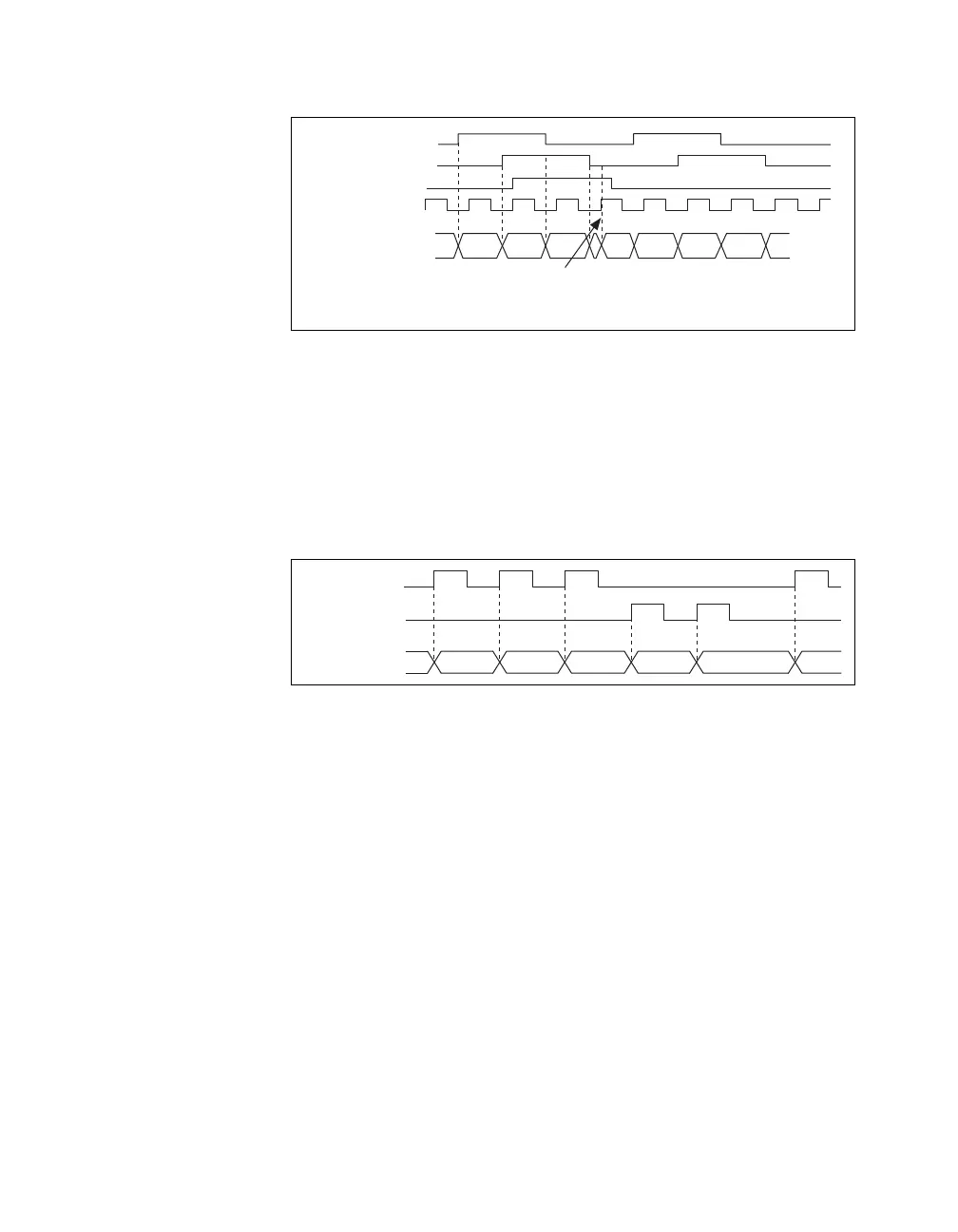
Figure 8-17. Channel Z Reload with X4 Decoding
Measurements Using Two Pulse Encoders
The counter supports two pulse encoders that have two channels—channels
A and B.
The counter increments on each rising edge of channel A. The counter
decrements on each rising edge of channel B, as shown in Figure 8-18.
Figure 8-18. Measurements Using Two Pulse Encoders
For information about connecting counter signals, refer to the Default
Counter/Timer Pinouts section.
Buffered (Sample Clock) Position Measurement
With buffered position measurement (position measurement using a
sample clock), the counter increments based on the encoding used after the
counter is armed. The value of the counter is sampled on each active edge
of a sample clock. A DMA controller transfers the sampled values to host
memory. The count values returned are the cumulative counts since the
counter armed event; that is, the sample clock does not reset the counter.
You can route the counter sample clock to the Gate input of the counter.
You can configure the counter to sample on the rising or falling edge of the
sample clock.
Ch A
Ch B
Counter Value
5 6
A = 0
B = 0
Z = 1
Ch Z
Max Timebase
8 9 0 2 1 7 4 3
Ch A
Ch B
Counter Value2 3 5 4 3 4 4

 Loading...


