Chapter 8 Counters
NI USB-621x User Manual 8-24 ni.com
You also can use the Gate input of the counter as a Pause Trigger (if it is not
used as a Start Trigger). The counter pauses pulse generation when the
Pause Trigger is active.
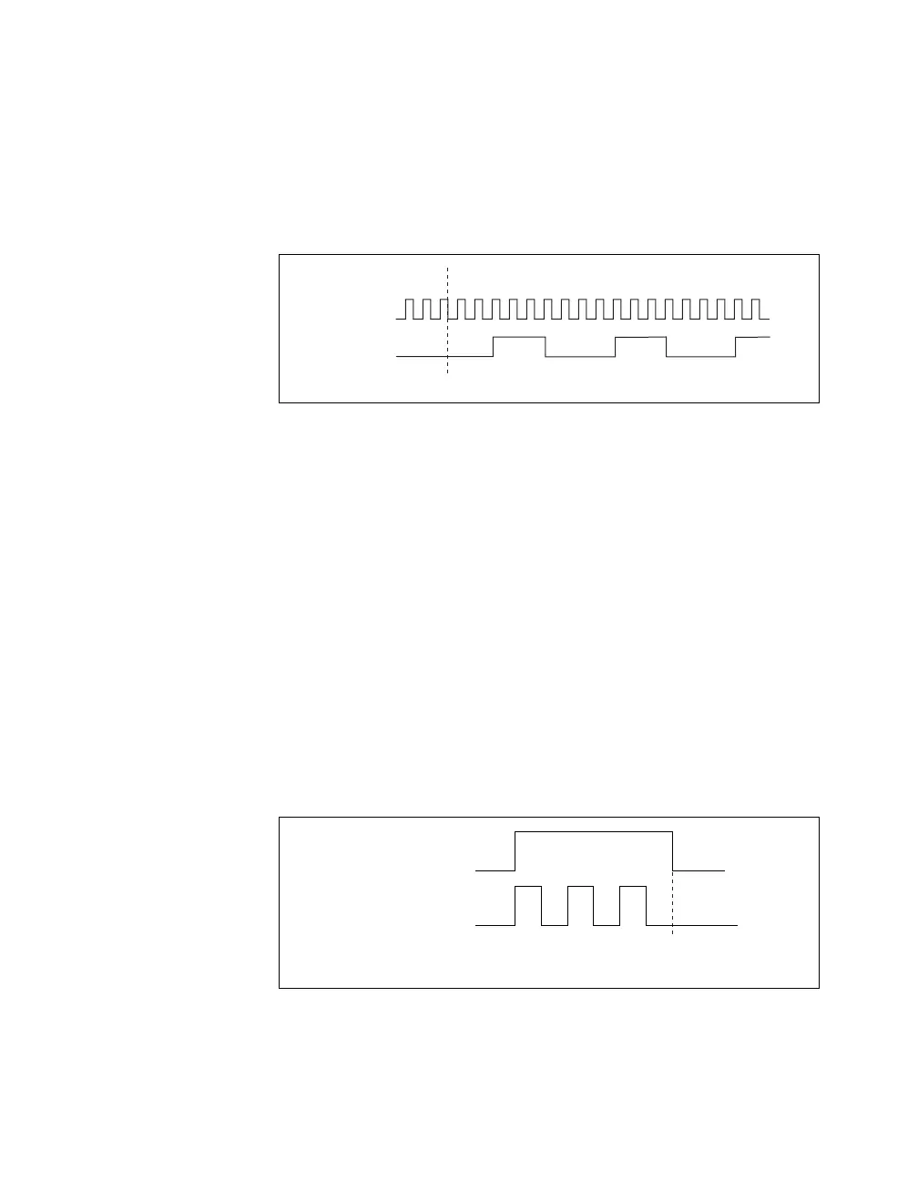
Figure 8-25 shows a continuous pulse train generation (using the rising
edge of Source).
Figure 8-25. Continuous Pulse Train Generation
Continuous pulse train generation is sometimes called frequency division.
If the high and low pulse widths of the output signal are M and N periods,
then the frequency of the Counter n Internal Output signal is equal to the
frequency of the Source input divided by M + N.
For information about connecting counter signals, refer to the Default
Counter/Timer Pinouts section.
Finite Pulse Train Generation
This function generates a train of pulses of predetermined duration. This
counter operation requires both counters. The first counter (for this
example, Counter 0) generates a pulse of desired width. The second
counter, Counter 1, generates the pulse train, which is gated by the pulse of
the first counter. The routing is done internally. Figure 8-26 shows an
example finite pulse train timing diagram.
Figure 8-26. Finite Pulse Train Timing Diagram
Counter 0
(Paired Counter)
Counter 1
Generation
Complete
 Loading...


