Chapter 5 Analog Output
© National Instruments Corporation 5-9 NI USB-621x User Manual
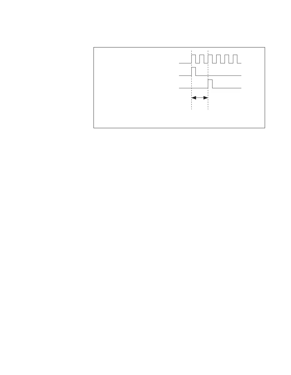
Figure 5-6 shows the relationship of AO Sample Clock to AO Start Trigger.
Figure 5-6. AO Sample Clock and AO Start Trigger
AO Sample Clock Timebase Signal
The AO Sample Clock Timebase (ao/SampleClockTimebase) signal is
divided down to provide a source for AO Sample Clock.
You can route any of the following signals to be the AO Sample Clock
Timebase signal:
•20MHzTimebase
• 100 kHz Timebase
•
(USB-6211/6215 Devices) PFI <0..3>
•
(USB-6212/6216 Devices) PFI <0..15>
•
(USB-6218 Devices) PFI <0..3>, PFI <8..11>
AO Sample Clock Timebase is not available as an output on the
I/O connector.
You might use AO Sample Clock Timebase if you want to use an external
sample clock signal, but need to divide the signal down. If you want to use
an external sample clock signal, but do not need to divide the signal, then
you should use AO Sample Clock rather than AO Sample Clock Timebase.
AO Sample Clock Timebase
AO Start Trigger
AO Sample Clock
Delay
From
Start
Trigger

 Loading...


