3-21 Hardware Installation
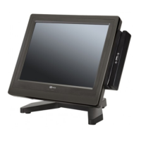
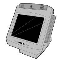
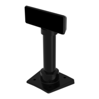
7. Connect the display to the post assembly.
8. Connect the terminal end of the Display Cable to the host terminal.
• RS–232 Interface (Powered)
Connect the I/F cable to a powered RS–232 connector on the terminal.
Configure the terminal serial port as follows:
• For NCR 5977 2x20 Customer Display
9600 baud, 8 data bits, 1 start bit, 1 stop bit, No parity
• For NCR 5977 Graphical Customer Display
38400 baud, 8 data bits, 1 start bit, 1 stop bit, No parity
• USB Interface (Powered)
Connect the I/F cable to a powered 12V USB + Power connector on the terminal.
• USB Interface (Non–Powered)
Connect the I/F cable to a non–powered USB connector on the terminal. Connect
a Power Brick to the I/F cable and an AC outlet.
 Loading...