Section 4: Optional Equipment
Aspila EX Hardware Manual Section 4: Optional Equipment 4-11
4
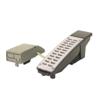
Installing a 110-Button DSS Console
1. Install an RJ11 (or RJ45) socket for each 110-Button DSS Console. The socket should be
within two metres of the console.
2. For each 110-Button DSS Console, run one-pair station cable to the RJ11 (or RJ45) socket.
3. Terminate the extension leads to pins 3 & 4 for RJ11 sockets (or pins 4 & 5 for RJ45 sockets).
4. Connect a line cord from the socket to the LINE connector on the bottom of the DSS console.
5. To program a DSS Console . . .
With the default settings, there are no DSS Consoles assigned.
10-03-01 : PCB Setup
The system automatically assigns the terminal type (10) for the port which has a DSS console
installed.
When installing a DSS, the system must auto-detect the console in order for the LEDS to
function correctly. When connecting the DSS to a extension previously defined with another
circuit type, undefine the circuit type (enter 00 in Program 10-03 for the extension number),
then connect the DSS Console.
30-02-01 : DSS Console Extension Assignment
Designate the extensions that have DSS Consoles connected to them.
30-03-01 : DSS Console Key Assignment
Customize the functions of the DSS Console keys.
30-04-01 : Alternate DSS Console Key Assignment
If the console should have Alternate Answering, use this program to assign the Alternate
Answering Destination.
 Loading...
