B-2
Memory Configurations
A DIMM socket accommodates a single 168-pin 60 ns
device with gold plated edge connectors as follows:
■
4M x 72 DIMM = 32MB
■
8M x 72 DIMM = 64MB
■
16M 72 DIMM = 128MB.
A DIMM should be installed in the bottom (J20) socket.
When you install additional DIMMs, you must start
with the first empty socket above DIMMs already
installed. When you remove DIMMs, you must start
with the first DIMM socket closest to the top edge of the
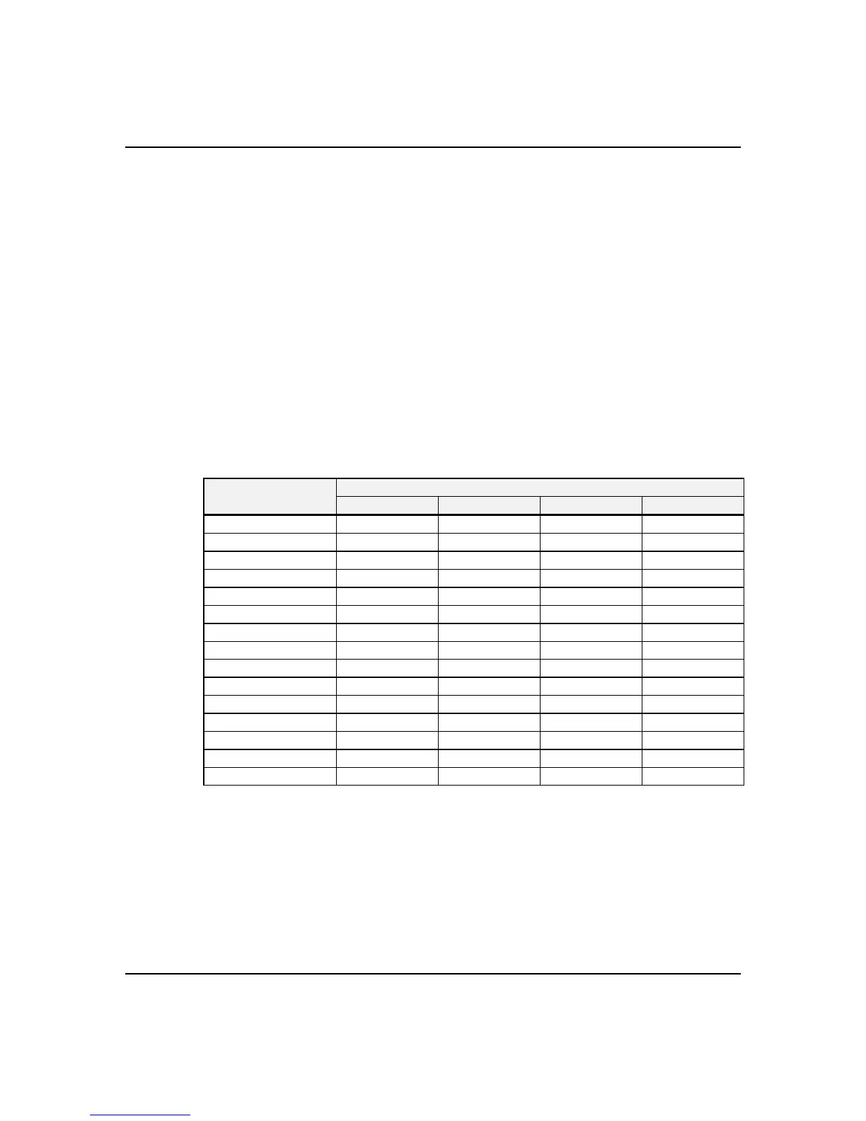
system board. Table B-1 lists the distribution of DIMMs
for system memory configurations.
Table B-1. Memory Configurations
System Capacity Capacity per DIMM slot (MB) Any DIMM slot order
(MB) J20 J19 J18 J17
32 32
64 64
96 64 32
128 128
160 128 32
192 128 64
224 128 64 32
256 128 128
288 128 128 32
320 128 128 64
352 128 128 64 32
384 128 128 128
416 128 128 128 32
448 128 128 128 64
512 128 128 128 128