86
6. Appendix
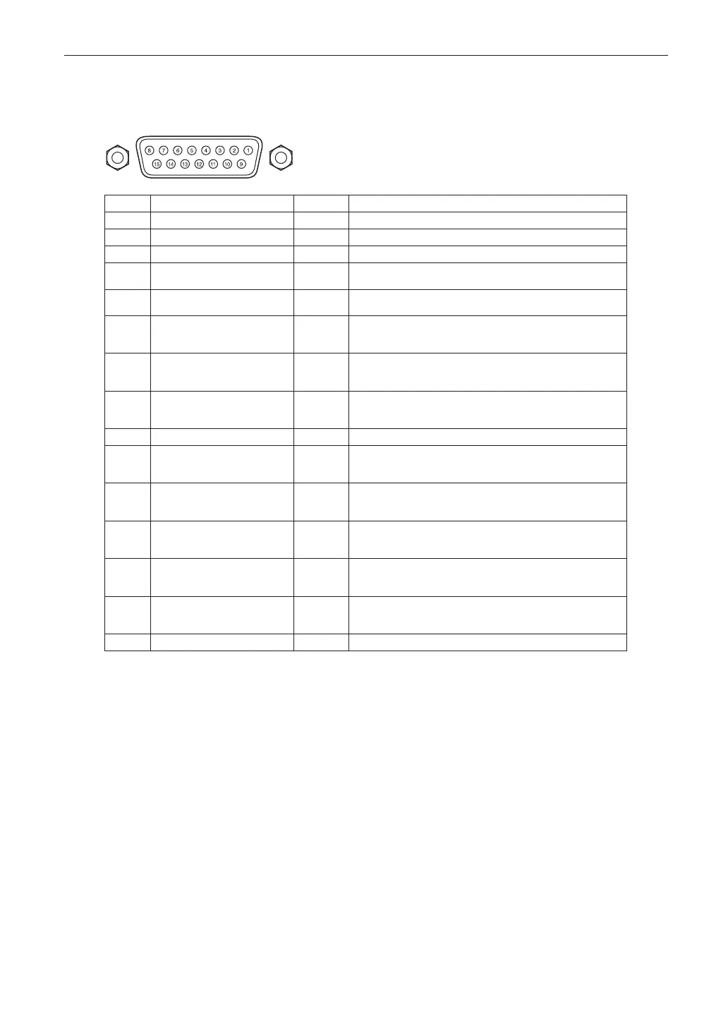
6-8-3. 3D connector (D-sub 15 pin)
This is used to connect a 3D image system to the projector.
Pin view of a female connector
Pin No. Signal Name I/O Function
1 +12V PWR Supplies power (+12V) to the 3D image system
2 GNDC GND Ground
3 GNDC GND Ground
4 RS232_RX IN Data transmission from the 3D image system
(1200 Baud, 8 bits, No Parity)
5 RS232_TX OUT Data transmission to the 3D image system
(1200 Baud, 8 bits, No Parity)
6 CONN_3D_MODE+ OUT 3D mode status (+)
(Connects to the collector of the output transistor of the
photo coupler inside the projector)
7 CONN_SYNC+ OUT 3D L/R switching timing signal (+)
(Connects to the collector of the output transistor of the
photo coupler inside the projector)
8 3D_INPUT_REFERENCE+ IN 3D L/R timing signal (+)
(Connects to the anode of the input diode of the photo
coupler inside the projector)
9 +12V PWR Supplies power (+12V) to the 3D image system
10 3D_INPUT_REFERENCE− IN 3D L/R timing signal (–)
(Connects to the cathode of the input diode of the photo
coupler inside the projector)
11 3D_DISPLAY_REFERENCE+ IN 3D L/R display timing signal (+)
(Connects to the anode of the input diode of the photo
coupler inside the projector)
12 3D_DISPLAY_REFERENCE− IN 3D L/R display timing signal (–)
(Connects to the cathode of the input diode of the photo
coupler inside the projector)
13 CONN_3D_MODE− OUT 3D mode status (–)
(Connects to the emitter of the output transistor of the photo
coupler inside the projector)
14 CONN_SYNC− OUT 3D L/R switching timing signal (–)
(Connects to the emitter of the output transistor of the photo
coupler inside the projector)
15 N/C − Unused